Appendix
A.5 Default Settings
SIPROTEC, 7SJ62/64, Manual
C53000-G1140-C207-2, Release date 01.2008
622
A.5.6 Pre-defined CFC Charts
Some CFC charts are already supplied with the SIPROTEC device. Depending on the variant the following
charts may be implemented:
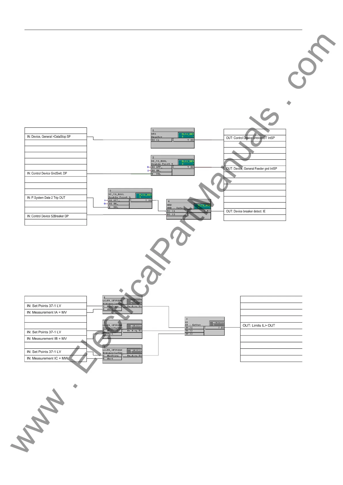
Device and System Logic
The NEGATOR block assigns the input signal „DataStop“ directly to an output. This is not directly possible
without the interconnection of this block.
Figure A-64 Logical links between input and output
Setpoints MV
Using modules on the running sequence ”measured value processing", a low current monitor for the three
phase currents is implemented. The output message is set high as soon as one of the three phase currents
falls below the set threshold:
Figure A-65 Undercurrent monitoring
www . ElectricalPartManuals . com

 Loading...


