Functions
2.12 Ground Fault Protection 64, 67N(s), 50N(s), 51N(s)
SIPROTEC, 7SJ62/64, Manual
C53000-G1140-C207-2, Release date 01.2008
226
2.12.2 Ground Fault Detection for U0/I0-ϕ Measurement
Voltage Element
The voltage element relies on a pickup initiated by the displacement voltage V
0
or 3 · V
0
. Additionally, the faulty
phase is determined. The displacement voltage V
0
can be directly applied to the device, or the summary
voltage 3 · V
0
can be calculated by the device based on the three phase–to–ground voltages. In the latter case,
the three voltage inputs must be connected to voltage transformers in a grounded-wye configuration (see also
address 213 VT Connect. 3ph in Subsection 2.1.3). If the device is only provided with phase-to-phase volt-
ages, it is not possible to calculate a displacement voltage from them. In this case the direction cannot be de-
termined.
If the displacement voltage is calculated, then:
3 · V
0
= V
A
+ V
B
+ V
C
If the displacement voltage is directly applied to the device, then V
0
is the voltage at the device terminals. It is
not affected by parameter Vph / Vdelta (address 206).
Pickup performed by the displacement voltage can be delayed (64-1 DELAY) for tripping.
It is important to note that the total trip-command time then consists of the displacement voltage measurement
time (about 50 ms) plus the pickup delay time 64-1 DELAY.
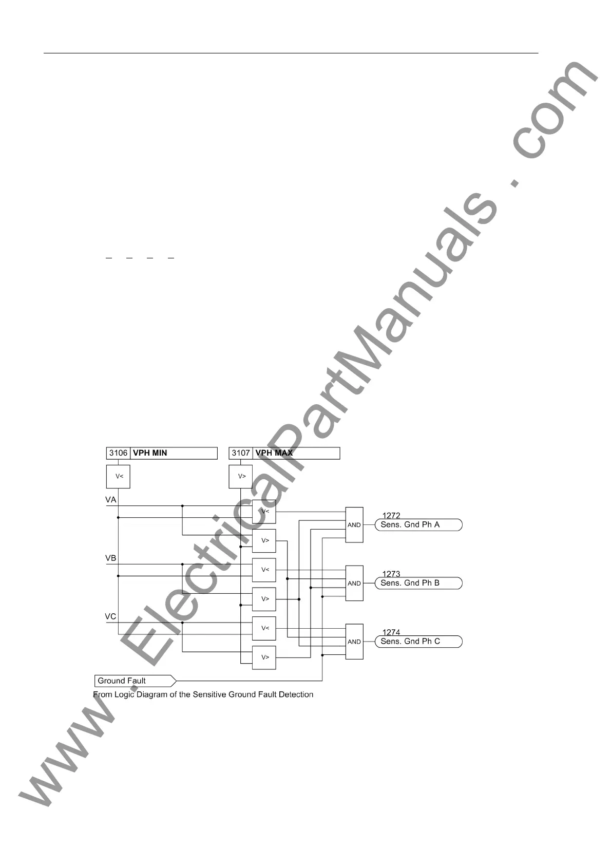
After the voltage element picks up due to detection of a displacement voltage, the grounded phase is identified,
if possible. To do this, the individual phase-to-ground voltages are measured. Of course, this is only possible if
three phase-to-ground voltages are obtained from voltage transformers connected in a grounded wye config-
uration. If the voltage magnitude for any given phase is below the setting value V
Ph min
, that phase is detected
as the grounded phase as long as the remaining phase-to-ground voltages are simultaneously above the
setting value V
Ph max
.
Figure 2-82 Determination of Ground-faulted Phase
www . ElectricalPartManuals . com

 Loading...


