Functions
2.17 Flexible Protection Functions
SIPROTEC, 7SJ62/64, Manual
C53000-G1140-C207-2, Release date 01.2008
291
Note
With regard to the phase-selective pickup messages, a special behavior is observed in the three-phase voltage
protection with phase-to-phase variables, because the phase-selective pickup message "Flx01 Pickup Lx" is
allocated to the respective measured-value channel "Lx".
Single-pole faults:
If, for example, voltage V
A
drops to such degree that the voltages V
AB
and V
CA
undershoot their threshold
values, the device indicates pickups “Flx01 Pickup A” and “Flx01 Pickup C”, because the undershooting was
detected in the first and third measured-value channel.
Two-pole faults:
If, for example, voltage V
AB
drops to such degree that its threshold value is undershot, the device then indicates
pickup "Flx01 Pickup A", because the undershooting was detected in the first measured-value channel.
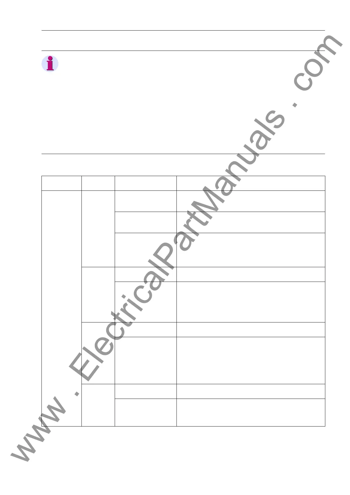
Table 2-23 Parameter in the Setting Dialog "Measurement Procedure", Mode of Operation 1-phase
Mode of Oper-
ation
Measured
Variable
Notes
Single-phase Current,
Voltage
Parameter
MEAS. METHOD
Setting Options
Fundamental Harmonic Only the fundamental harmonic is evaluated, higher harmonics
are suppressed. This is the standard measurement procedure
of the protection functions.
True RMS The „True“ RMS value is determined, i.e. higher harmonics are
evaluated. This procedure is applied, for example, if an over-
load protection element must be realized on the basis of a
current measurement, as the higher harmonics contribute to
thermal heating.
Current Parameter CURRENT
Setting Options
IA
IB
IC
IN
INS
IN2
It is determined which current-measuring channel must be eval-
uated by the function. Depending on the device version, either
IN (normal-sensitive ground current input), INS (sensitive
ground current input) or IN2 (second ground current connected
to the device) can be selected.
Voltage Parameter VOLTAGE
Setting Options
VAB
VBC
VCA
VAN
VBN
VCN
VN
It is determined which voltage-measuring channel must be
evaluated by the function. When selecting phase-to-phase volt-
age, the threshold value must be set as a phase-to-phase
value, when selecting a phase-to-ground variable as phase-to-
ground voltage. The extent of the setting texts depends on the
connection of the voltage transformer (see address 213 VT
Connect. 3ph).
P forward,
P reverse,
Q forward,
Q reverse
Parameter POWER
Setting Options
IA VAN
IB VBN
IC VCN
It is determined which power-measuring channel (current and
voltage) must be evaluated by the function. With phase-to-
phase voltage connections the parameter is hidden (see
address 213 VT Connect. 3ph).
www . ElectricalPartManuals . com

 Loading...


