Functions
2.25 Breaker Control
SIPROTEC, 7SJ62/64, Manual
C53000-G1140-C207-2, Release date 01.2008
386
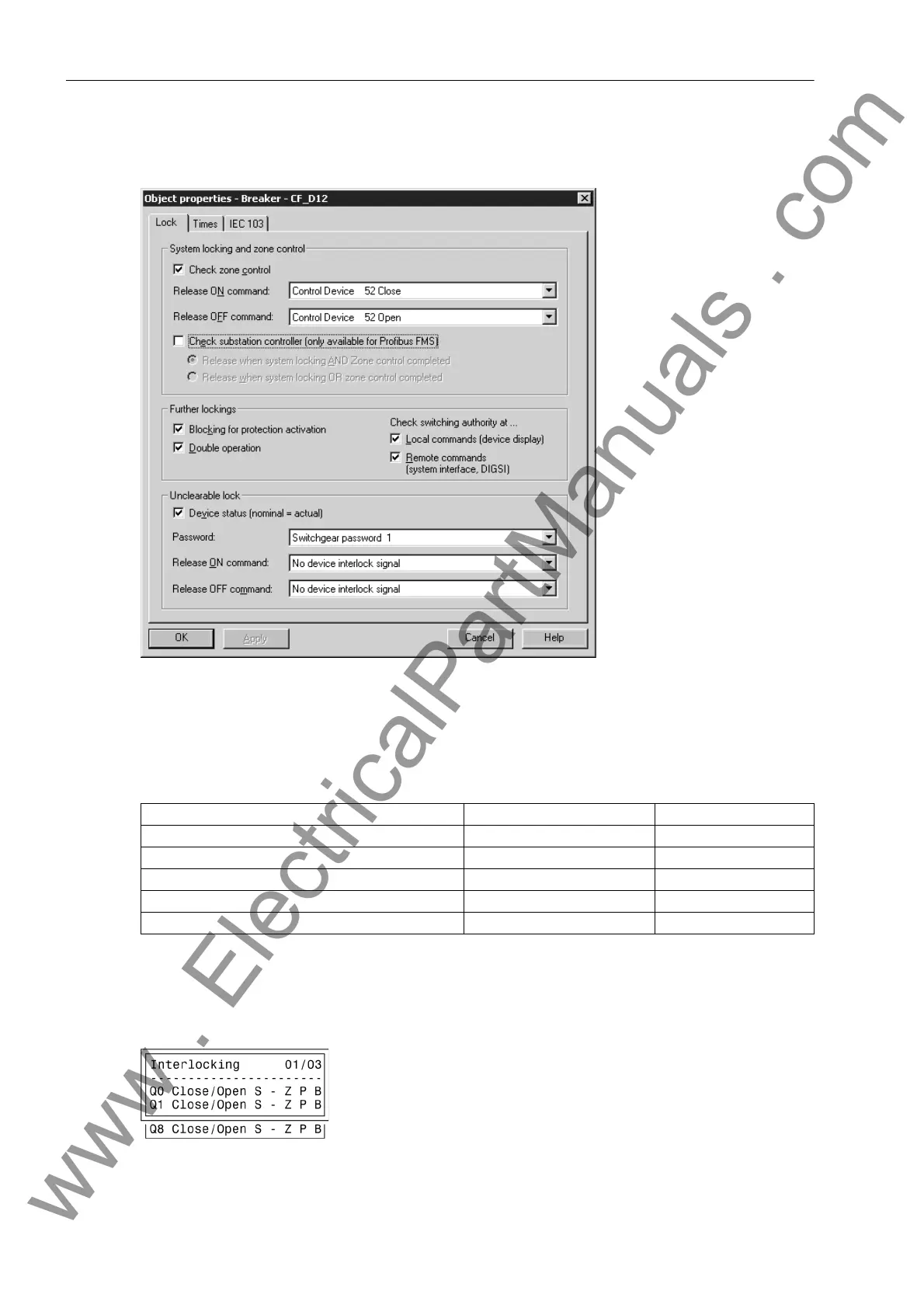
The following figure shows the configuration of the interlocking conditions using DIGSI.
Figure 2-146 DIGSI dialog box for setting the interlocking conditions
On devices with operator panel, the display shows the configured interlocking reasons. They are marked with
letters explained in the following table.
Table 2-29 Command types and corresponding messages
The following figure shows all interlocking conditions (which usually appear in the display of the device) for
three switchgear items with the relevant abbreviations explained in the previous table. All parameterized inter-
locking conditions are indicated.
Figure 2-147 Example of configured interlocking conditions
Interlocking Commands Abbrev. Display
Switching Authority L L
System interlocking S A
Zone controlled Z Z
SET = ACTUAL (switch direction check) P P
Protection blocking B B
www . ElectricalPartManuals . com

 Loading...


