Mounting and Commissioning
3.3 Commissioning
SIPROTEC, 7SJ62/64, Manual
C53000-G1140-C207-2, Release date 01.2008
455
• If not, first check whether one of the aforesaid messages 170.2090 „25 V2>V1“, 170.2091 „25 V2<V1“
170.2094 „25 α2>α1“ or 170.2095 „25 α2<α1“ is available in the spontaneous messages.
Messages „25 V2>V1“ or „25 V2<V1“ indicate that the magnitude matching is incorrect. Check address
6X21 Balancing V1/V2 and recalculate the adaptation factor.
The messages „25 α2>α1“ or „25 α2<α1“ indicate that the phase relation of the busbar voltage does
not match the setting under address CONNECTIONof V2 (see Section2.19.1). When measuring via a trans-
former, address 6x22 ANGLE ADJUSTM. must also be checked. This must adapt the vector group. If
these are correct, there is probably a reverse polarity of the voltage transformer terminals V
1
.
• For the synchrocheck the program SYNC V1>V2< is set to YES (address 6x08) and SYNC Function X is
set to ASYN/SYNCHRON (address 16x).
• Open the VT mcb of the busbar voltage.
• Via binary input (170.0043 „>25 Sync req.“) initiate the measuring request. There is no close release.
If there is, the VT mcb for the busbar voltage is not allocated. Check whether this is the required state, al-
ternatively check the binary input „>FAIL: BUS VT“ (6510).
• Close the VT mcb of the busbar voltage again.
• Open the circuit breaker.
• For the synchrocheck the program SYNC V1<V2> is set to YES (address 6x07) and SYNC V1>V2< is set
to NO (address 6x08).
• Via binary input (170.0043 „>25 Sync req.“) initiate the measuring request. The synchronism check
must release closing (message „25 CloseRelease“, 170.0049). Otherwise check all voltage connections
and the corresponding parameters again carefully as described in Section 2.19.1.
• Open the VT mcb of the feeder voltage.
• Via binary input (170.0043 „>25 Sync req.“) initiate the measuring request. No close release is given.
• Close the VT mcb of the feeder voltage again.
Addresses 6x07 to 6x10 must be restored as they were changed for the test. If the routing of the LEDs or
signal relays was changed for the test, this must also be restored.
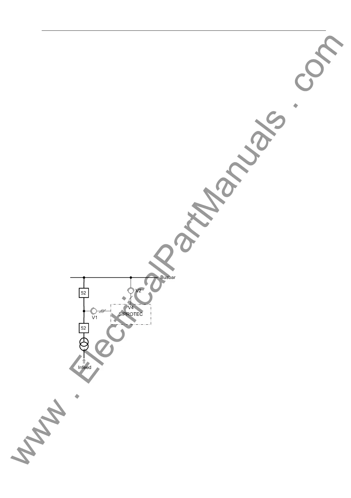
Figure 3-36 Measuring voltages for the synchro-check
www . ElectricalPartManuals . com

 Loading...


