Functions
2.1 General
SIPROTEC, 7SJ62/64, Manual
C53000-G1140-C207-2, Release date 01.2008
46
The assignment of the protection functions to the ground current inputs in special connections is set out in the
following table.
The settings for address 251 are only possible with DIGSI under Additional Settings.
Note
The settings under address 251 CT Connect. affect the time overcurrent protection with regard to the eval-
uation of phase currents only if address 250 50/51 2-ph prot has been set to OFF.
Voltage Connection (Power System)
Adress 213 determines how the voltage transformers are connected. VT Connect. 3ph = Van, Vbn, Vcn
means that three phase voltages are connected in wye-connection, VT Connect. 3ph = Vab, Vbc, VGnd
signifies that two phase-to-phase voltages (V-connection) and V
N
are connected. The latter setting also has to
be selected when only two phase-to-phase voltage transformers are used or when only the displacement
voltage (zero sequence voltage) is connected to the device.
The devices 7SJ623, 7SJ624 and 7SJ64 contain 4 voltage measuring inputs which enable further options in
addition to the above-mentioned connection types: VT Connect. 3ph = Van,Vbn,Vcn,VGn is selected if
the three phase voltages in wye-connection and V
N
are connected to the fourth voltage input of the device.
Select VT Connect. 3ph = Van,Vbn,Vcn,VSy in case the fourth voltage input is used for the synchroniza-
tion function. This is recommended even if two phase-to-phase voltages (V-connection) are available on the
primary side (because the voltages are connected to the device in such a way that the device measures phase-
to-ground voltages under symmetrical conditions).
Parameter 240 VT Connect. 1ph is set to specify that only one voltage transformer is connected to the de-
vices. In this case, the user defines which primary voltage is connected to which analog input. If one of the avail-
able voltages is selected, i.e. a setting unequal NO, setting of address 213 is not relevant anymore. Only the
setting of parameter 240 is relevant. If, however, parameter 240 VT Connect. 1ph is set to NO, parameter
213 will be valid.
In case of a single-phase voltage transformer connection, devices 7SJ623, 7SJ624 and 7SJ64 always interpret
the voltage applied at voltage input V
4
as the voltage that needs to be synchronized.
Note
If the synchronization function is used in a connection of two phase-to-phase voltages in V-connection (see
above), the device is unable to determine a zero-sequence voltage. The functions „Directional Time Overcur-
rent Protection Ground“, „Directional Ground Fault Detection“ and „Fuse Failure Monitoring (FFM)“ must be
either removed or switched off.
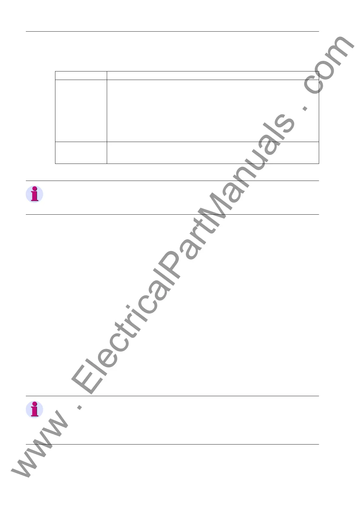
Current input Function
I
N2
Time overcurrent protection ground (Section 2.2)
Directional time overcurrent protection ground (Section 2.3)
Important!
The function „Directional time overcurrent protection ground“ may only be operated if the
ground current of the protected line is measured via I
N2
. This is not the case for the
example shown in Figure 2-3. Here, the ground current of the protected line is measured
via I
N
. The function must be deactivated. A connection in which the function can be
enabled is illustrated in the Appendix A.3 Figure A-41.
I
N
or I
N sensitive
Ground fault detection (sensitive / not sensitive) (Section 2.12)
Single-phase time overcurrent protection (Section 2.5)
Intermittend ground fault protection (Section 2.13)
www . ElectricalPartManuals . com

 Loading...


