Functions
2.2 Overcurrent Protection 50, 51, 50N, 51N
SIPROTEC, 7SJ62/64, Manual
C53000-G1140-C207-2, Release date 01.2008
74
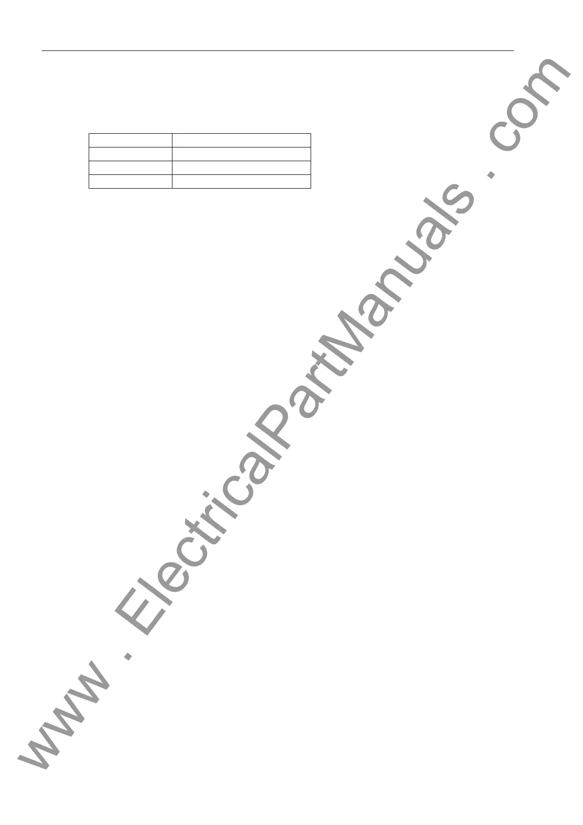
Switching to the lower pickup value or decreasing the pickup threshold is carried out phase-selectively. The
assignment of voltages to current-carrying phases is shown in the following table.
Table 2-2 Controlling voltages in relation to the fault currents
In order to avoid an unwanted operation in case of a voltage transformer fault, a function blocking is implement-
ed via a binary input controlled by the voltage transformer protection breaker as well as via the device-internal
measuring voltage failure detection ("Fuse Failure Monitor").
The following two figures show the logic diagrams for the inverse time overcurrent protection with undervoltage
consideration.
Current Voltage
I
A
V
A
– V
B
I
B
V
B
– V
C
I
C
V
C
– V
A
www . ElectricalPartManuals . com

 Loading...


