Functions
6-76 7SJ63 Manual
C53000-G1140-C120-1
Implementation In-
structions
In an ungrounded system, the reactive component of the current should be used to
determine the direction. In a grounded system, the real component of the current
should be used to determine the direction. Therefore, in an ungrounded system, ad-
dress should be set for 6,13+, measurement whereas in a grounded system,
address should be set for &263+, measurement.
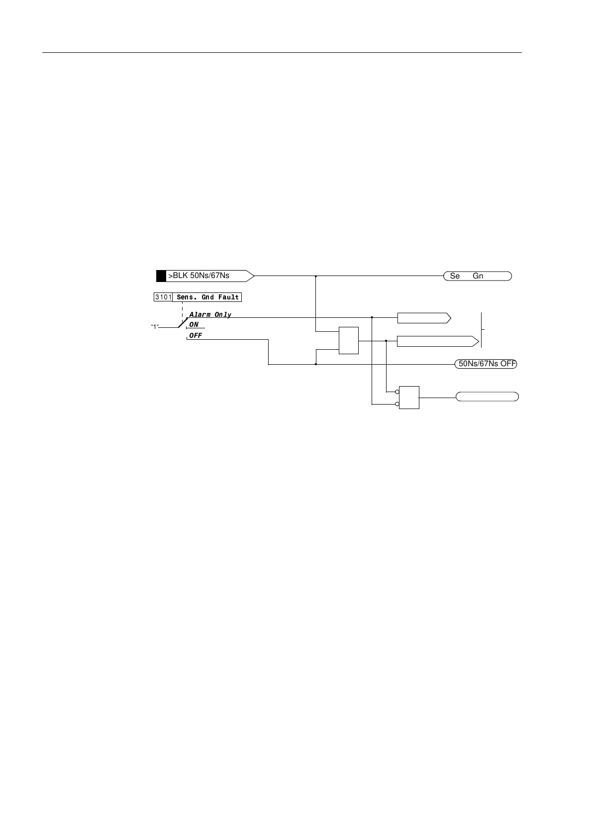
Logic Figure 6-34 illustrates the condition logic for the sensitive ground fault pickup. Ground
fault pickup may be switched 21 or 2)), or into $ODUP2QO\ condition at address
6HQV*QG)DXOW. When ground fault protection is 21, tripping is possible.
The entire function may be blocked via a binary input. Switching off or blocking means
the measurement logic (shown in Figure 6-35) is deactivated, therefore, time delays
and messages are reset.
Figure 6-34 Activation of Sensitive Ground Fault Detection
or
21
$ODUP2QO\
6HQV*QG)DXOW
“1“
2))
50Ns/67Ns OFF
>BLK 50Ns/67Ns
Sens. Gnd block
&
50Ns/67Ns ACT
F# 1207
F# 1230
F# 1211
F# 1212
Reset Measurement Logic
Alarm Only
to Figure
6-35
www . ElectricalPartManuals . com

 Loading...


