Installation and Commissioning
8-177SJ63 Manual
C53000-G1140-C120-1
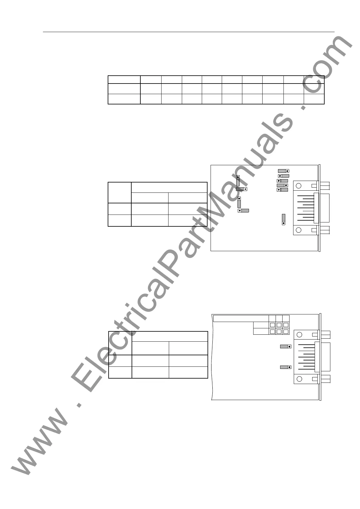
Jumpers X5 through X10 must be set on the same position!
The jumpers are set at the factory based on the configuration ordered.
Jumpers X3 and X4 for bus termination are shown in Figure 8-11 for an RS 485 inter-
face and in Figure 8-12 for a Profibus interface.
Figure 8-11 Location of the Jumpers for Configuring the Terminating Resistors of the
Interface
Jumpers X3 and X4 are set at the factory so that the terminating resistors are
switched-out. Both jumpers must always be set on the same position.
Figure 8-12 Location of the Jumpers for Configuring the Profibus–Interface Terminating
Resistors
Table 8-9 Configuration of Jumpers for RS 232 or RS 485 on the Interface Card (Circuit
Board Number C53207-A322-B80, Figure 8-11)
Jumper X5 X6 X7 X8 X9 X10 X11 X12 X13
RS 232 1–2 1–2 1–2 1–2 1–2 1–2 2–3 1–2 1–2
RS 485 2–3 2–3 2–3 2–3 2–3 2–3 2–3 1–2 1–2
X3
132
X10
132
8X
1
3
2
X12
132
C53207-
A324-B180
1
3
2
X11
X6
X7
X4
X5
132
1
3
2
X13
Jumper
Terminating Resistors
Connected Disconnected
X3 2-3
1-2
*
)
X4 2-3
1-2
*
)
*
) Factory Set
X3
312
X4
312
Jumper
Terminating Resistors
Connected Disconnected
X3 1-2
2-3
*
)
X4 1-2
2-3
*
)
C53207-A322-
234
B100
B101
*
) Factory Set
www . ElectricalPartManuals . com

 Loading...


