3RT1/3RH1 contactors
SIRIUS System Manual
3-36
GWA 4NEB 430 0999-02b
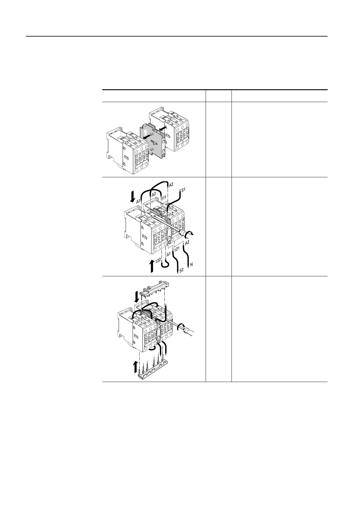
The following table shows you the components of the kit for the contactor
combination for reversing in frame size S0 and explains how to put it
together:
Table 3-17: Assembling the contactor combination for reversing (frame size S0)
Drawing: frame size S0 Step Procedure
1/2
Mount the mechanical inter-
lock between the two contac-
tors.
3
Wire the actuating voltage and
the electrical reversing interlock
using the auxiliary conducting
paths.
4/5
Attach the wiring modules
(4)
in order to connect the main
conducting paths and tighten
the terminals
(5)
.
2
1
3
3
4
4
5
 Loading...