System overview
SIRIUS System Manual
GWA 4NEB 430 0999-02b
1-15
1.5 Mounting methods and terminal systems
1.5.1 Mounting the equipment
The method of mounting the equipment is uniform within each frame size.
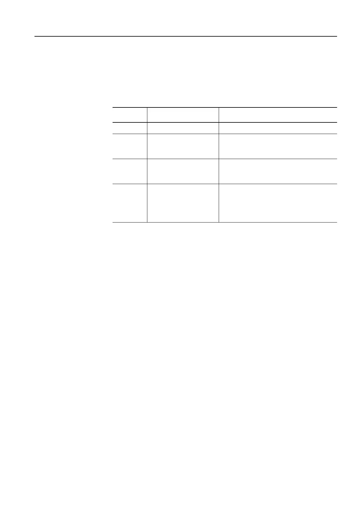
Table 1-2: Mounting methods
Screw-on mounting
The SIRIUS switching devices can be screwed on to a flat surface.
Please note the following points with some of the devices:
• 3RV1 circuit breaker, frame sizes S00/S0: Push-in lugs are required for
screw-type mounting
• 3RP15 time relay: Push-in lugs are required for screw-type mounting
• Coupling links: No screw-type mounting
• Soft starters: No screw-type mounting
Snap-on mounting
The SIRIUS switching devices are snapped onto 35 mm rails in acc. with
DIN EN 50 022 without a tool.
The devices with a frame size of S3 require a rail with an installation height
of 15 mm. Alternatively, they can also be snapped onto 75 mm rails.
Frame size Mounting Removal
S00 to S3 Screwed on Removed with a screwdriver
S00, S0 Snapped onto a
35 mm rail (in acc. with
DINEN50022)
Removed without a tool
S2 Snapped onto a
35 mm rail (in acc. with
DINEN50022)
The snap-on spring can be opened with a
screwdriver
S3 Snapped onto a
35 mm rail (in acc. with
DINEN50022)
Snapped onto a
75 mm rail
The snap-on spring can be opened with a
screwdriver
 Loading...