3RT1/3RH1 contactors
SIRIUS System Manual
GWA 4NEB 430 0999-02b
3-77
Installation
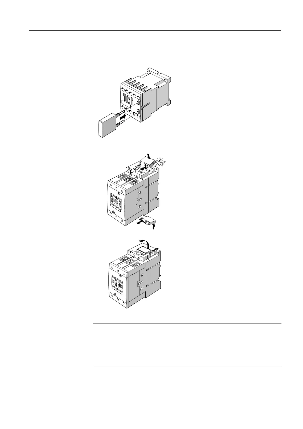
Figure 3-59: Surge suppressors, installation
Installation instruc-
tions for frame sizes
S0 to S3
Important
The 3RT1926-1E.00 diode combination is inserted from above. The direction
of attachment is defined by a code.
Alternatively, the 3RT1926-1T.00 diode combination can be inserted from
below. The direction of attachment is not coded, but the terminals are mar-
ked with "+" and "-" so that the direction is clear.
Frame size S00
The surge suppressor is attached
on the front of the contactors.
There is space next to the
attached auxiliary switch block.
The direction of for attachment is
defined by a code.
Frame sizes S0 to S3
Varistors, RC elements, and
diode combinations can either be
inserted and snapped on from
above or below directly onto the
coil terminals.
To remove them, press the varis-
tors, RC elements, and diode
combinations forwards, and
remove them from the recess.
2
1
2
1
1
2
 Loading...