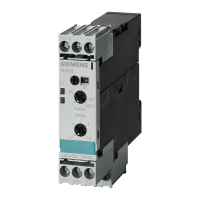
SIRIUS System Manual
GWA 4NEB 430 0999-02b
vii
Figures
Figure 1-1: SIRIUS system. . . . . . . . . . . . . . . . . . . . . . . . . . . . . . . . . . . . . . . . . . . . . 1-5
Figure 1-2: Circuit breaker, accessories (frame size S00) . . . . . . . . . . . . . . . . . . . . . . . . . . 1-6
Figure 1-3: Circuit breakers, accessories (frame sizes S0, S2, and S3) . . . . . . . . . . . . . . . . . . 1-6
Figure 1-4: Contactors, accessories (frame size S00) . . . . . . . . . . . . . . . . . . . . . . . . . . . . 1-7
Figure 1-5: Contactors, accessories (frame sizes S0 to S3). . . . . . . . . . . . . . . . . . . . . . . . . 1-8
Figure 1-6: Device combinations . . . . . . . . . . . . . . . . . . . . . . . . . . . . . . . . . . . . . . . . . 1-13
Figure 1-7: Contactor combination for reversing . . . . . . . . . . . . . . . . . . . . . . . . . . . . . . . 1-14
Figure 1-8: Cage Clamp terminal . . . . . . . . . . . . . . . . . . . . . . . . . . . . . . . . . . . . . . . . . 1-18
Figure 1-9: Conductor cross-sections £ 1 mm² . . . . . . . . . . . . . . . . . . . . . . . . . . . . . . . . 1-20
Figure 1-10: Communication . . . . . . . . . . . . . . . . . . . . . . . . . . . . . . . . . . . . . . . . . . . . 1-22
Figure 2-1: 3RV1 circuit breakers (frame sizes S00 to S3). . . . . . . . . . . . . . . . . . . . . . . . . . 2-5
Figure 2-2: Setting the current setting I
e
(example: frame size S00) . . . . . . . . . . . . . . . . . . . 2-7
Figure 2-3: Sealing the adjustment scale (frame size S00) . . . . . . . . . . . . . . . . . . . . . . . . . 2-8
Figure 2-4: Tripped position, 3RV (frame size S0). . . . . . . . . . . . . . . . . . . . . . . . . . . . . . . 2-9
Figure 2-5: Locking the toggle switch (frame size S00) . . . . . . . . . . . . . . . . . . . . . . . . . . . 2-9
Figure 2-6: Time-current characteristic, chart . . . . . . . . . . . . . . . . . . . . . . . . . . . . . . . . . 2-11
Figure 2-7: Frequency sensitivity of the n-short-circuit releases . . . . . . . . . . . . . . . . . . . . . . 2-12
Figure 2-8: Circuit breaker with overload relay function (frame sizes S0 to S3) . . . . . . . . . . . . 2-14
Figure 2-9: Circuit diagrams of circuit breakers for fuse monitoring. . . . . . . . . . . . . . . . . . . . 2-15
Figure 2-10: Mounting the transverse auxiliary switch (frame size S00) . . . . . . . . . . . . . . . . . . 2-19
Figure 2-11: Mounting/removing the lateral auxiliary switch/undervoltage release (frame size S00) 2-20
Figure 2-12: Mounting the disconnecting module (frame size S0) . . . . . . . . . . . . . . . . . . . . . 2-26
Figure 2-13: Locking the disconnecting module (frame size S0) . . . . . . . . . . . . . . . . . . . . . . 2-27
Figure 2-14: Locking the disconnecting module and mounting the cover (frame size S2) . . . . . . . 2-27
Figure 2-15: Mounting the rotary switch extension for the door (frame size S2) . . . . . . . . . . . . 2-28
Figure 2-16: Operating the rotary switch extension for the door . . . . . . . . . . . . . . . . . . . . . . 2-29
Figure 2-17: Locking the rotary switch extension for the door. . . . . . . . . . . . . . . . . . . . . . . . 2-30
Figure 2-18: Terminals for "Combination Motor Controller Type E" . . . . . . . . . . . . . . . . . . . . . 2-31
Figure 2-19: Molded-plastic surface casing (frame size S00). . . . . . . . . . . . . . . . . . . . . . . . . 2-32
Figure 2-20: Molded-plastic bay (frame size S00). . . . . . . . . . . . . . . . . . . . . . . . . . . . . . . . 2-33
Figure 2-21: Mounting the front plate (frame size S00) . . . . . . . . . . . . . . . . . . . . . . . . . . . . 2-34
Figure 2-22: Mounting the front plate (frame size S0). . . . . . . . . . . . . . . . . . . . . . . . . . . . . 2-34
Figure 2-23: Accessories for the housings and front plates (frame size S00). . . . . . . . . . . . . . . 2-35
Figure 2-24: Indicator light installation in a molded-plastic housing. . . . . . . . . . . . . . . . . . . . . 2-36
Figure 2-25: Mounting circuit breakers on busbar adapters (frame sizes S00 and S0) . . . . . . . . . 2-38
Figure 2-26: Mounting circuit breakers on busbar adapters (frame sizes S2 and S3) . . . . . . . . . . 2-39
Figure 2-27: Accessories for busbar adapters (frame sizes S00 to S2) . . . . . . . . . . . . . . . . . . 2-40
Figure 2-28: 3-phase busbar system. . . . . . . . . . . . . . . . . . . . . . . . . . . . . . . . . . . . . . . . 2-41
Figure 2-29: Mounting the isolated 3-phase busbar system (frame sizes S00 to S0) . . . . . . . . . . 2-43
Figure 2-30: Mounting the isolated 3-phase busbar system (frame size S2) . . . . . . . . . . . . . . . 2-44
Figure 2-31: Mounting the circuit breakers onto the rail. . . . . . . . . . . . . . . . . . . . . . . . . . . . 2-45
Figure 2-32: Screw-on mounting of the 3RV1 (example: frame size S00) . . . . . . . . . . . . . . . . . 2-45
Figure 2-33: Circuit breaker, soldering pin connector (frame size S00) . . . . . . . . . . . . . . . . . . 2-47
Figure 2-34: Device circuit diagram (frame size S00). . . . . . . . . . . . . . . . . . . . . . . . . . . . . . 2-48
Figure 2-35: Device circuit diagrams (frame sizes S0 to S3) . . . . . . . . . . . . . . . . . . . . . . . . . 2-48
Figure 2-36: Circuit breaker with relay function, device circuit diagrams (frame sizes S0 to S3) . . . 2-48
Figure 2-37: 3RV10 11, 3RV16 (frame size S00), 3RV10 21 (frame size S0) . . . . . . . . . . . . . . . 2-49
Figure 2-38: 3RV10 31 (frame size S2) . . . . . . . . . . . . . . . . . . . . . . . . . . . . . . . . . . . . . . 2-49
Figure 2-39: 3RV10 4 (frame size S3) . . . . . . . . . . . . . . . . . . . . . . . . . . . . . . . . . . . . . . . 2-49
Figure 2-40: 3RV11 21 (frame size S0), 3RV11 31 (frame size S2) . . . . . . . . . . . . . . . . . . . . . 2-50

 Loading...


