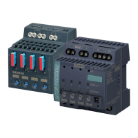
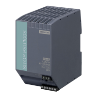
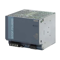
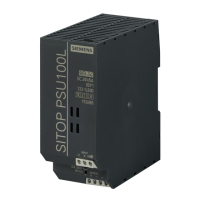
SITOP expansion modules
Equipment Manual, 09.2022, A5E36605235-2-76
11
Table of contents
Overview ................................................................................................................................................ 3
1 Safety instructions ............................................................................................................................... 15
1.1 General safety instructions ................................................................................................. 15
1.2 Safety instructions for hazardous zones .............................................................................. 16
1.2.1 Redundancy module SITOP RED1200 Ex (6EP4347-7RC00-0AX0) ........................................ 16
1.2.2 Buffer module SITOP BUF1200 Ex (6EP4231-7HC00-0AX0) ................................................. 16
2 Description, device design, dimension drawing ................................................................................. 17
2.1 Device description ............................................................................................................. 17
2.1.1 Redundancy modules ......................................................................................................... 17
2.1.1.1 SITOP RED1200 .................................................................................................................. 17
2.1.1.2 SITOP PSE202U .................................................................................................................. 18
2.1.2 Buffer modules .................................................................................................................. 21
2.1.2.1 SITOP BUF1200 .................................................................................................................. 21
2.1.2.2 SITOP PSE201U .................................................................................................................. 22
2.1.3 Inrush current limiter ......................................................................................................... 23
2.1.3.1 Logo! ICL230 ..................................................................................................................... 23
2.1.3.2 SITOP inrush current limiter ............................................................................................... 24
2.2 Connections and terminal designation ............................................................................... 25
2.2.1 Redundancy modules ......................................................................................................... 25
2.2.1.1 SITOP RED1200 .................................................................................................................. 25
2.2.1.2 SITOP PSE202U .................................................................................................................. 26
2.2.2 Buffer modules .................................................................................................................. 27
2.2.2.1 SITOP BUF1200 .................................................................................................................. 27
2.2.2.2 SITOP PSE201U ..................................................................................................................
28
2.2.3 Inrush current limiter ......................................................................................................... 29
2.2.3.1 Logo! ICL230 ..................................................................................................................... 29
2.2.3.2 SITOP inrush current limiter ............................................................................................... 30
2.3 Potentiometer ................................................................................................................... 31
2.3.1 SITOP PSE202U redundancy modules ................................................................................. 31
2.4 Status displays and signaling .............................................................................................. 32
2.4.1 SITOP PSE202U redundancy modules ................................................................................. 32
2.4.2 Buffer modules .................................................................................................................. 33
2.4.2.1 SITOP BUF1200 .................................................................................................................. 33
2.4.2.2 SITOP PSE201U .................................................................................................................. 33
2.4.3 Inrush current limiter ......................................................................................................... 34
2.4.3.1 Logo! ICL230 ..................................................................................................................... 34
2.4.3.2 SITOP inrush current limiter ............................................................................................... 35

 Loading...


