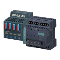
SITOP expansion modules
Equipment Manual, 09.2022, A5E36605235-2-76
55
Mounting position, mounting clearances
4.1 Standard mounting position
Expansion modules must be mounted vertically in such a way that
- 6EP1961-3BA21 terminals are at the bottom
- 6EP1962-2BA00 terminals "OK" and "OUT 24V" are at the bottom
- 6EP1964-2BA00 terminals "OK" and "OUT 24V" are at the bottom
- 6EP1961-3BA01 terminals are at the bottom
- 6EP1967-2AA00 input terminals are at the top and the output terminals at the bottom.
A clearance of at least 50 mm should be maintained above and below the device; no
clearance is required at the sides.
The SITOP RED1200 redundancy modules must be mounted vertically to ensure correct
cooling so that
- 6EP4346-7RB00-0AX0 terminals are at the bottom
- 6EP4347-7RB00-0AX0 and 6EP4347-7RC00-0AX0 terminals are at the bottom
- 6EP4348-7RB00-0AX0 terminals are at the bottom.
A clearance of at least 45 mm should be maintained above and below the device; no
clearance is required at the sides.
The SITOP BUF1200 buffer module must be mounted vertically to ensure correct cooling so
that for
- 6EP4231-7HB00-0AX0 and 6EP4231-7HC00-0AX0, the terminals are at the bottom.
A clearance of at least 45 mm should be maintained above and below the device; no
clearance is required at the sides.
The LOGO! ICL230 inrush limiter must be mounted vertically to ensure correct cooling so that
- 6EP4683-6LB00-0AY0 output terminals are at the top and the input terminals at the bottom.
A clearance of at least 20 mm should be maintained above and below the device; no
clearance is required at the sides.

 Loading...


