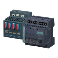
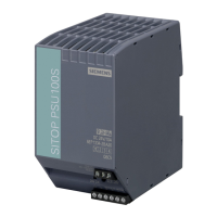
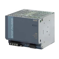
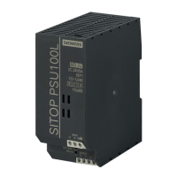
Description, device design, dimension drawing
2.3 Potentiometer
SITOP expansion modules
Equipment Manual, 09.2022, A5E36605235-2-76
31
2.3 Potentiometer
2.3.1 SITOP PSE202U redundancy modules
The potentiometer ④ at the front of the device is used to set the response threshold of the
LED signal and the signaling contact; it can be set in the range from 20 V up to 25 V. (when
delivered, 20 V)
Figure 2-17 Potentiometer 6EP1961-3BA21
Figure 2-18 Potentiometer 6EP196x-2BA00 (example 6EP1962-2BA00)
It is only permissible to use an insulated screwdriver when actuating the potentiometer.
For notes on actuating the potentiometer (screwdriver, torque), see Figure 2-11 Terminal
data 6EP1961-3BA21 (Page 26) and Figure 2-12 Terminal data 6EP1962-2BA00 and 6EP1964-
2BA00 (Page 27).

 Loading...


