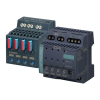
Description, device design, dimension drawing
2.1 Device description
SITOP expansion modules
18 Equipment Manual, 09.2022, A5E36605235-2-76
2.1.1.2 SITOP PSE202U
Redundancy modules SITOP PSE202U are the optimum addition to all 24 V power supplies to
provide additional protection against failure of the 24 V supply. The redundancy module
continuously monitors the feeding power supplies, and when one device fails, the other one
automatically takes over the complete 24 V supply.
The failure of a 24 V power supply is signaled using an LED and a relay contact. The response
threshold for this signal can be set between 20 V and 25 V using a potentiometer on the
redundancy module. (when delivered, 20 V)
With redundancy module NEC class2, a redundant 24 V power supply can be implemented,
where the output power is limited to 100 VA.
24 V input – supply voltage from power supplies 1 and 2
24 V output – supply voltage to the load and 0 V connection to the internal supply
Floating relay contact (changeover contact)
Figure 2-2 Design 6EP1961-3BA21

 Loading...


