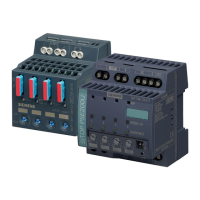
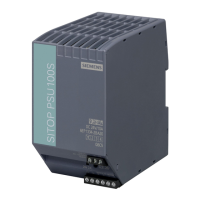
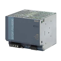
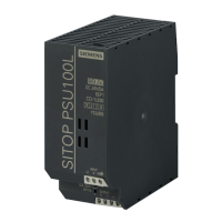
Description, device design, dimension drawing
2.2 Connections and terminal designation
SITOP expansion modules
Equipment Manual, 09.2022, A5E36605235-2-76
27
Connections and terminal designations of the redundancy modules 6EP1962-2BA00 and
① Input 24 V supply voltage from power supplies
1 and 2 "IN 24V-1", "IN 24V-2"
0 V connection to the internal supply "GND"
Plug-in terminal each with a screw terminal
② Output 24 V supply voltage to the load "OUT
24 V"
floating relay contact "O.K."
Plug-in terminal with one screw terminal (output)
and two screw terminals (relay contact)
*1)
Do not subject the end stop to higher loads
Figure 2-12 Terminal data 6EP1962-2BA00 and 6EP1964-2BA00
2.2.2 Buffer modules
2.2.2.1 SITOP BUF1200
Use copper wire certified for at least 75 °C.
Connections and terminal designations
① 24 V DC supply voltage "+", "-"
1 spring-loaded terminal each

 Loading...


