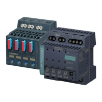
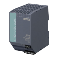
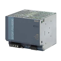
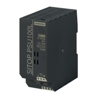
Description, device design, dimension drawing
2.2 Connections and terminal designation
SITOP expansion modules
26 Equipment Manual, 09.2022, A5E36605235-2-76
Figure 2-10 Terminal data 6EP4347-7RB00-0AX0, 6EP4348-7RB00-0AX0 and 6EP4347-7RC00-0AX0
2.2.1.2 SITOP PSE202U
Use suitable copper cables that are designed for operating temperatures of at least 60/75
°C.
The cables must be certified for at least 90 °C for the 6EP1964-2BA00 device.
Connections and terminal designations of redundancy module 6EP1961-3BA21
① Input 24 V supply voltage of power supplies 1
and 2 "IN 24 V-1", "IN 24 V-2"
② Output 24 V supply voltage to the load / "OUT
24 V"
0 V connection to the internal supply "GND"
③ Floating relay contact (changeover contact)
"OK"
Plug-in terminal 3 screw terminals
*1)
Do not subject the end stop to higher loads
*2)
2
for square crimping, otherwise 10 mm
2
Figure 2-11 Terminal data 6EP1961-3BA21

 Loading...


