Connecting
3.1 Transmitter Wiring
FUT1010 IP65 NEMA 4X & IP66 NEMA 7 Liquid Quick Start
26 Operating Instructions, 1/2013, A5E02639182-AC
3.1.2 Connecting Sensor Cables to Transmitter
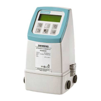
1. Open the transmitter top cover. Using a flat blade screwdriver, remove the Cable Strain
Relief bracket.
83
'1
83
'1
&+$11(/
&+$11(/
'8$/&+$11(/
,138702'8/(
83
83
'1
'1
① Transmitter Input Module ⑤ To CH-2 UP
② Transducer Cables Connected to
Transmitter
⑥ To CH-1 DN
③ Cable Strain Relief Bracket ⑦ To CH-1 UP
④ To CH-2 DN ⑧ Channel 2 to Junction Box
⑨ Channel 1 to Junction Box
Figure 3-2 Sensor Cable Connections
2. Observing the upstream to downstream orientation, pull Sensor cables through
transmitter cable glands.
3. Attach the Sensor cables to Channel 1 and Channel 2 UP and DN Input Module F-
connectors. Repeat for additional paths as necessary.
4. Replace the Cable Strain Relief bracket. Close transmitter top cover.
5. If not installing a Temperature Sensor, proceed to Sensor Wiring.

 Loading...


