Additional Installation Instructions
B.1 Direct mount
FSS200 clamp-on sensors
92 Installation Manual, 08/2017, A5E36255466-AC
11.Disassemble the spacer bar and the unmounted frame. Use the bar as a straight edge
and, with one edge against the mounted frames tapered roller center and the other
crossing the dot you drew, draw a line crossing the dot (see "B" above). Set the bar
aside.
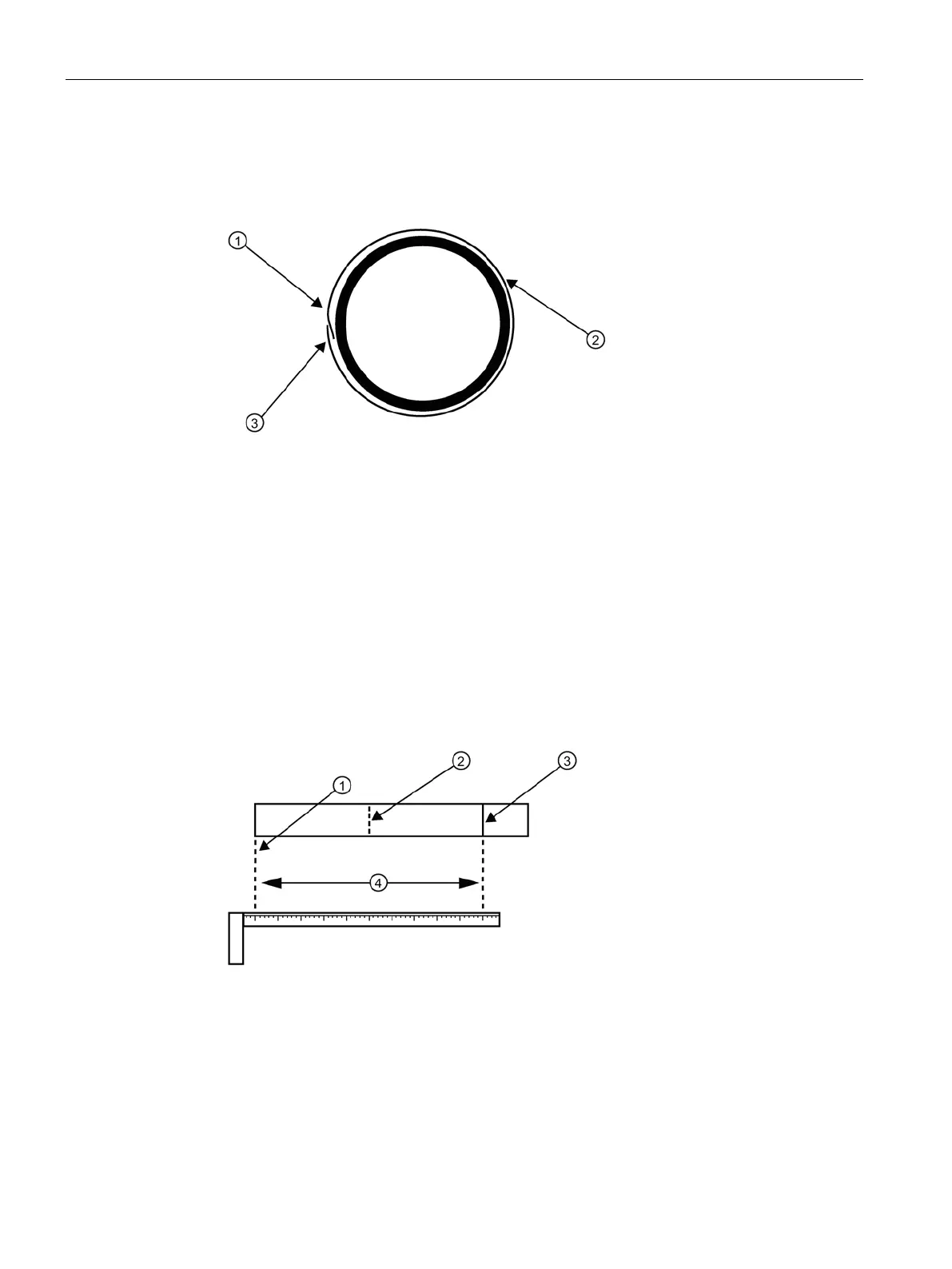
Trim material from inner edge if necessary
8 cm (3-inch) Overlapping Edge
Figure B-3 Wrapping the Mylar spacing guide around the pipe (end view)
12.Wrap the Mylar spacing guide around the pipe so that the left edge is against the sensor
edge mark (see "C" above). Arrange so that one end overlaps the other by at least three
inches. Trim to fit if necessary, but be sure not to trim at the overlapping end in order to
keep it square.
13.Realign left edge of the guide with the sensor edge mark. Line up both vertical edges of
the guide and ensuring that it is snug around the pipe, mark along the overlapping edge.
14.Remove Mylar spacing guide and lay it out on a flat surface. Either measure the exact
distance half-way between the overlap edge and the mark at the overlap, or fold the
guide from the overlap edge to overlap mark and draw a line at the fold or halfway point.
Mark (or fold) exactly at half-way point
Figure B-4 Finding the halfway distance
15.Reinstall the spacing guide; its left edge abutting the sensors edge mark on the pipe and
the overlapping edge in line with the dot (now a line) on the pipe (see "C"). Tape it in this
position on the pipe. Take the second frame and place it against the edge of the guide
with its tapered roller centered on the center mark on the guide.

 Loading...


