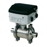
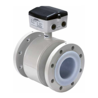
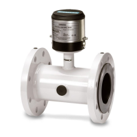
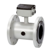
2.3.3 FM Class I, II, III, Div 1 approval
Compact version for MAG 3100/3100 P sensors DN 15 to 300 (½" to 12")
Hazardous area
Class I, Div. 1, Group A, B, C, D
User I/O interface
Passive current
(31, 32)
Active current
(31, 32)
Relay
(44, 45, 46)
Frequency/pulse
(56, 57)
Profi (FISCO)
(95, 96)
Digital input
(77, 78)
ABCD CD AB ABCD ABCD ABCD ABCD
U
i
28 V DC U
O
30 V DC 30 V DC U
i
30 V DC U
i
28 V DC U
i
17.5 V DC U
i
30 V DC
I
I
100 mA I
O
87.8 mA 86.8 mA I
I
200 mA I
I
100 mA I
I
380 mA I
I
C
I
19.7 nF C
O
557 nF 63 nF C
I
3.3 nF C
I
14.2 nF C
I
0 nF C
I
0 nF
L
I
36 µH L
O
18.4 mH 4.6 mH L
I
0 µH L
I
36 µH L
I
0 µH L
I
0 µH
P
I
0.7 W P
O
0.66 W 0.66 W P
I
1.2 W P
I
1.2 W P
I
5.32 W P
I
1.2 W
Notes from control drawing
1. The non-intrinsically safe terminals (power rail) must not be connected to a device which
uses or generates more than 250/30 Vrms or DC.
2. The installation must meet the requirements of the National Electrical Code/Canadian
Electrical Code.
3. Conduit seal is required within 460 mm (18") from MAG 6000 I in hazardous areas (Class
I, Div. 1).
The control drawings are found on the CD-ROM shipped with the device and on the Siemens
homepage at http://www.siemens.com/flowdocumentation.
See also
Control drawing (Page 97)
Safety notes
2.3 Installation in hazardous area
18
SITRANS MAG 6000 I/6000 I Ex de
Operating Instructions, 08/2018, A5E02083319-AH

 Loading...


