39
SIVACON S8 Planning Principles – Universal mounting design
2
3
4
5
6
7
8
9
10
11
1
4.3.1 Withdrawable design - standard
feature design (SFD)
The withdrawable units provide a fixed contact system.
Disconnected, test and connected position can be effected
by moving the withdrawable unit (Fig. 4/6). In discon-
nected or test position, degree of protection IP30 is
achieved. Moving the withdrawable unit under load is
prevented by an operating error protection.
Withdrawable units in SFD provide a detachable cover.
Controls and signalling devices are installed in an instru-
ment panel and integrated into the withdrawable unit
cover (Fig. 4/7). The contact system can be applied up to a
rated current of 250 A. All withdrawable units are equipped
with up to 40 auxiliary contacts. In SFD, normal withdrawa-
ble units with a withdrawable unit height of 100 mm or
higher (grid size 50 mm) can be used. Tab. 4/8 summarizes
the characteristics of withdrawable units in SFD.
Mechanical withdrawable unit coding
Withdrawable unit height
100 mm
15 coding options
Withdrawable unit height
> 100 mm
21 coding options
Locking capability
In "0" position for 3UC7
door coupling rotary drive
Up to 5 padlocks
with a shackle diameter of 4.5 mm
Up to 3 padlocks
with a shackle diameter of 8.5 mm
Instrument panel
Max. installation depth for
devices
60 mm
Usable front area if
withdrawable unit height
100 mm
198 mm
57 mm
Usable front area if
withdrawable unit height
> 100 mm
198 mm
97 mm
Withdrawable unit position signal
With optional signalling
switch (-S20)
Feeder available signal
Test position signal
Communication interfaces
PROFIBUS
1)
(up to 12 Mbit/sec)
Via auxiliary contacts of the control
plug
PROFINET
2)
Separate RJ45 plug
1)
Apart from that, other protocols based on the EIA-485 (RS485) interface
standard such as Modbus RTU can be used
2)
Apart from that, other protocols based on the Industrial Ethernet standard
such as Modbus/TCP can be used
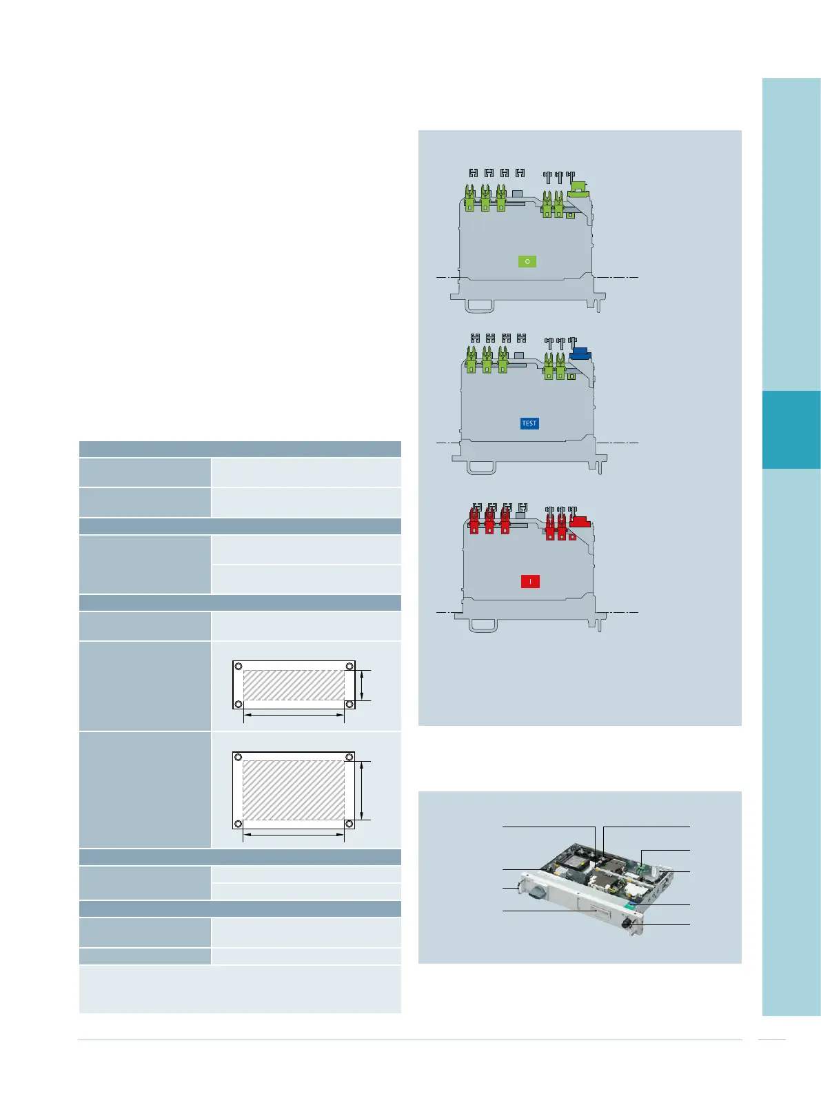
Fig. 4/6: Positions in the SFD contact system
Disconnected
position
Test
position
Connected
position
Fig. 4/7: Normal withdrawable unit in SFD with a withdrawable
unit height of 100 mm
Instrument panel
Handle
Basic withdrawable unit
Control plug
Position indicator
(option)
Unlock knob
Device plate
to be equipped from two sides,
depth/height staggered
Contact enclosure
output
Contact enclosure
input
Tab. 4/8: Characteristics of withdrawable units in SFD

 Loading...


