75
SIVACON S8 Planning Principles – Further planning notes
2
3
4
5
6
7
8
9
10
11
1
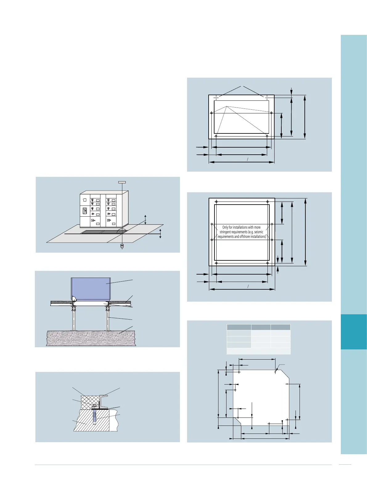
Foundation frame and floor mounting
The foundation generally consists of concrete, with a cut-
out for cable or busbar entry. The cubicles are positioned
on a foundation frame made of steel girders. In addition to
the permissible deviations of the installation area (Fig. 8/5),
it must be ensured that
• The foundation is precisely aligned
• The butt joints of more than one foundation frame are
smooth
• The surface of the frame is in the same plane as the
surface of the finished floor
Two typical examples for switchboard installation are:
• Installation on a raised floor (Fig. 8/6)
• Foundation frame mounted on concrete (Fig. 8/7)
For the mounting point on the foundation frame, please
see Fig. 8/8 for single-front and Fig. 8/9 for double-front
systems. Fig. 8/10 shows dimensions of the corner cubicle.
Dimensions in mm are referred to the cubicle widths W and
cubicle depth D.
Fig. 8/10: Mounting points for the corner cubicle
25
75
D
350
25
25
25
75
350
100
100
61
B
D
B
B D
500 350 500
600 450 600
650 800
Holes
7 x Ø14.8
M12
Field depth
All dimensions in mm
103.6
800 / 1,200
Fig. 8/5: Permissible deviations of the installation area
1 mm / m
1 mm / m
Fig. 8/6: Installation on raised floors
Adjustable post
Concrete floor
Floor plate,
inserted
Switchboard
Box girder of
foundation
Fig. 8/7: Foundation frame mounted on concrete
Bolt
Screed
Foundation frame,
e.g. U-shaped section DIN 1026
Heavy-duty dowel
Concrete floor
Alignment shims
Fig. 8/8: Mounting points of the single-front system
A A
25
W
+2
-1
D -50
75
25
W -150
D
W - 50
350
Alternative to A
4 x Ø14.8
All dimensions in mm
Fig. 8/9: Mounting points of the single-front system
25
W
+2
-1
D -50
75
25
W -150
D
W - 50
350
350
Only for installations with more
stringent requirements (e.g. seismic
requirements and offshore installations)
4 holes Ø14.8
All dimensions in mm

 Loading...


