PROFIBUS Interface Center
SPC3
Page 28 V1.3 SPC3 Hardware Description
2003/04 Copyright (C) Siemens AG 2003. All rights reserved.
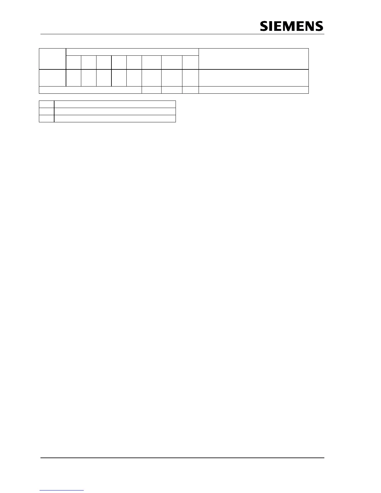
Address Bit Position Designation
RAM
Register
Cfg
Set_
Prm
R_Aux_Puf_Sel
X1 X1 X1 See below for coding.
X1 Coding
0 Aux_Buffer1
1 Aux_Buffer2
Figure 6.2: Aux-Buffer Management
The user makes the configuration data (Get_Config) available in the Read_Cfg buffer for reading. The
Read_Cfg buffer must have the same length as the Cfg_buffer.
The Read_Input_Data telegram is operated from the Din buffer in the ‘D state’, and the Read_Output_Data
telegram is operated from the Dout buffer in the ‘U state.’
All buffer pointers are 8-bit segment addresses, because the SPC3 internally has only 8-bit address
registers. For a RAM access, SPC3 adds an 8-bit offset address to the segment address shifted by 3 bits
(result: 11-bit physical address). As regards the buffer start addresses, this results in an 8-byte graunularity
from this specification.