10.6 Connection diagrams
You can connect a frost protection unit to the input. It must be connected according
to the following diagram:
Connection diagram,
frost protection unit
G
G
G0
X...
G0
N
3101A15
AC 24 V
M
F3
T
X... M
You can connect a passive LG-Ni1000 temperature sensor to the input. It must be
connected according to the following diagram:
Connection diagram,
water
G
G
G0
X... M
G0
F3a
N
3101A17
AC 24 V
You can connect an active temperature sensor with a DC 0…10 V = 0…15 °C
signal to the input. It must be connected according to the following diagram:
Connection diagram,
air
G
G
G0
G0
N
3101A16
AC 24 V
X... M
G1
F3b
B
MG
F3 QAF63.2 frost protection unit with capillary (air)
Legend for the
connection diagrams
F3a QAE2120.010 immersion temperature sensor (water)
F3b QAM2161.040 frost sensor (air)
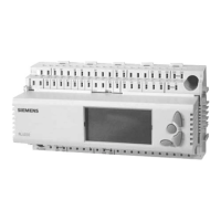
N RLU2… universal controller
146 / 174
Siemens Universal Controllers RLU2… CE1P3101en
Building Technologies Frost protection (FROST) 29.08.2008

 Loading...


