12 Electrical connections
12.1 Connection rules
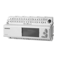
The following picture shows the terminal base of the RLU236 controller with its
connections:
Terminal connection
concept
– Extra-low-voltage side at the top
– Mains voltage side at the bottom
MM MM M MM G1 G0Y2 G0 G0
X1 X2 G1 X3 X4 G1 X5 D2D1 G1 G0Y3 G1 G0Y1 G G
Q14
Q24 Q34 Q44 Q64
Q11 Q11 Q23 Q23 Q33Q33 Q43 Q43 Q63 Q63Q53 Q53
NPE
Q12
Q54Q42
Pump
Extra-low-voltage side
Mains voltage side
Sytem power supply
AC 24 V
Power supply
AC 230 V
Double terminal
with internal
connection
Support terminals
in cabinet
Passive sensors /
signaling elements /
contact sensing
Active sensors /
signaling elements
Actuator
DC 0...10 V
3101A18en
Pump
Terminal Intended for …
Xx, M Passive sensors and signal sources, potential-free contacts
(contact sensing)
G1, Xx , M Active sensors and signal sources.
G1, Yx, M Actuators
G and G0 AC 24 V system power supply
Terminal assignment
Only one solid or one stranded wire can be connected per terminal.
Note
Connection procedure
with spring cage
terminals
1. 2. 3.
3140Z13
Steps 1. Strip the wire over a length of 7…8 mm
2. Position the wire and screwdriver (size 0 to 1)
3. Apply pressure with the screwdriver while inserting the wire
4. Remove screwdriver
150 / 174
Siemens Universal Controllers RLU2… CE1P3101en
Building Technologies Electrical connections 29.08.2008

 Loading...


