Operating Manual Matrix
Copyright Silca 201212
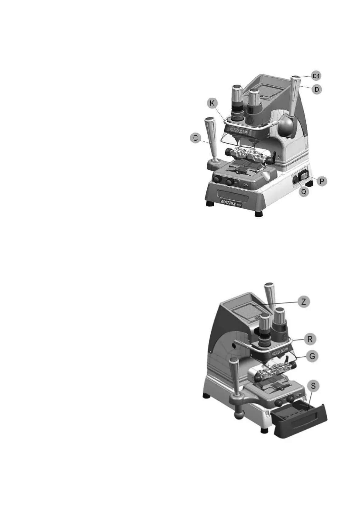
7.5 WORK STATION DESCRIPTION
The machine is operated by a single person using the following controls:
• ON/OFF master switch (P) located on the right-
hand side of the machine.
• Motor ON/OFF switch (Q).
• Vertical carriage lever (D) with push button (D1) to
release the lever and start the motor.
• Clamp unit
• Lever (left-hand) (C)
• Key pad (calibration and illumination) (K)
Fig. 12
• ORGANIZER SHELF (Z)
The top part of the cover incorporates an area for the operator to use as a place for things such as key blanks or
cut keys. It is advisable not to put too many things in this area, as they could accidentally fall off.
• ROLLBAR (R)
The purpose of this special bar is to assist the operator
during key cutting. It is used as a rest for the left hand when
moving the clamp carriage (centering cuts on dimple keys or
cutting path for laser keys). It ensures smooth synchronised
carriage movements during cutting operations.
• TRANSPARENT SAFETY SHIELD (G)
Special plexiglass shield to limit the dispersal of swarf.
• TOOL BOX (S)
In the bottom part of the machine front, under the clamp
unit carriage, there is a tool box with an open part to use as
a handle for pulling out the box. Inside it has 20 spaces for
holding tracer points and cutters, and a larger area for other
small tools and/or keys.
Fig. 13