User Manual For - CONTROLLER/DATA RECORDER MultiCon CMC-99/141
see
Fig.
4.8
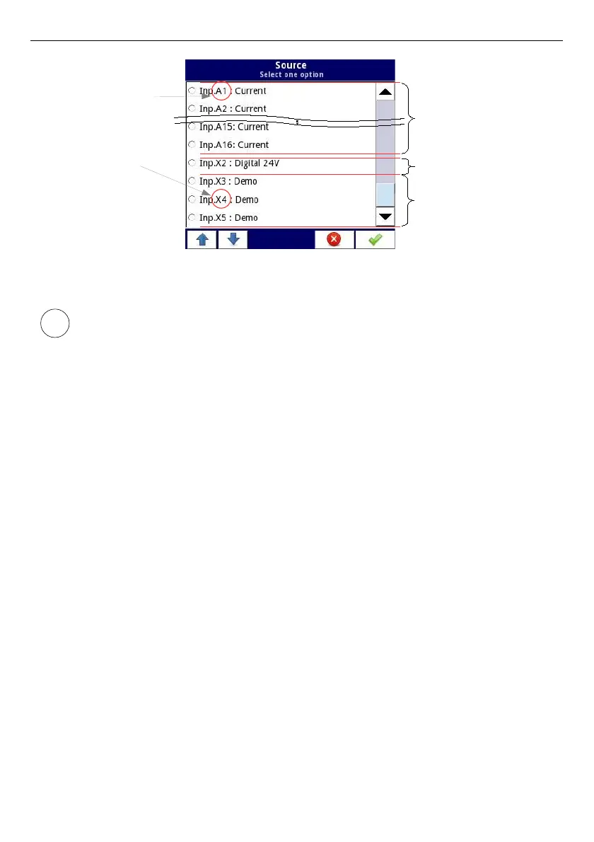
Fig. 7.48. The view of a sample list of available hardware inputs for a device
In the device there are two methods to change the source configuration of the
Built-in inputs
:
•
using the
Configure source
button in the
Logical channel
menu in
the
Hardware input
mode,
•
using the
Built-in inputs
menu,
The
Source
for the
Hardware input
mode can be (in the same order as the list in the device -
see
Fig.
7.48
):
a) installed
input modules
in the appropriate slots A, B or C (see
Fig.
4.8
) - the list of
currently available modules is on the website,
A Description of the input modules parameters is shown in
Chapter 7.9.2. Built-in inputs -
Input modules
.
The following steps change the
Source configuration
for the sample of 3 modules shown in
Fig.
7.49
:
– Step
(1)
- selection of the
Source
for the channel in the
Hardware input
mode, for
example:
Inp.A1:Current
, next press the
Configure source
button to enter
the
Source configuration
menu,
– Step
(2)
- press the
Mode
button to change the range of the current input,
– Step
(3)
- choose from the list of available options for the signal range - for example:
Current 0-20mA
(for the current module),
95
i
Slot A, Input 1
Slot X (built-in slot)
Input 4
I16 Module
16 current inputs
Built-in binary input
Built-in Demo input

 Loading...