1-4
The 4100 operator interface panel shows the following under normal conditions.
• Green power LED is ON – indicating the panel is receiving AC Power.
• All other LEDs off.
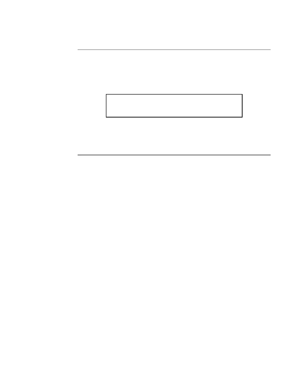
• Alphanumeric display reports that the system is normal, as shown below.
Note: If the appearance of the operator interface panel is not as
shown above, refer to the information in Chapters 2, 3, and 4 for
instructions on managing the alarm, supervisory, or trouble
condition.
Normal Appearance of Operator Interface Panel
Description
SYSTEM IS NORMAL
08:23:45 MON 18-SEPT-00
Technical Manuals Online! - http://www.tech-man.com