10 - 13
8. Tip the seat forward to access the battery compart-
ment. Through the round access hole in the frame
(A, Figure 21), remove the capscrew and washers
securing the shift lever (D, Figure 22) to the to the
transmission shift shaft (E). Disconnect the lever (D)
from the transmission.
9. Remove the capscrews (J, Figure 23) securing the
torsion bar retainers (I) and rotate the torsion bar out
of the way.
10.Remove the front and back capscrews (G and K,
Figure 23) securing the transmission to the carrier.
11.Using the floor jack, lower the transmission out of the
carrier.
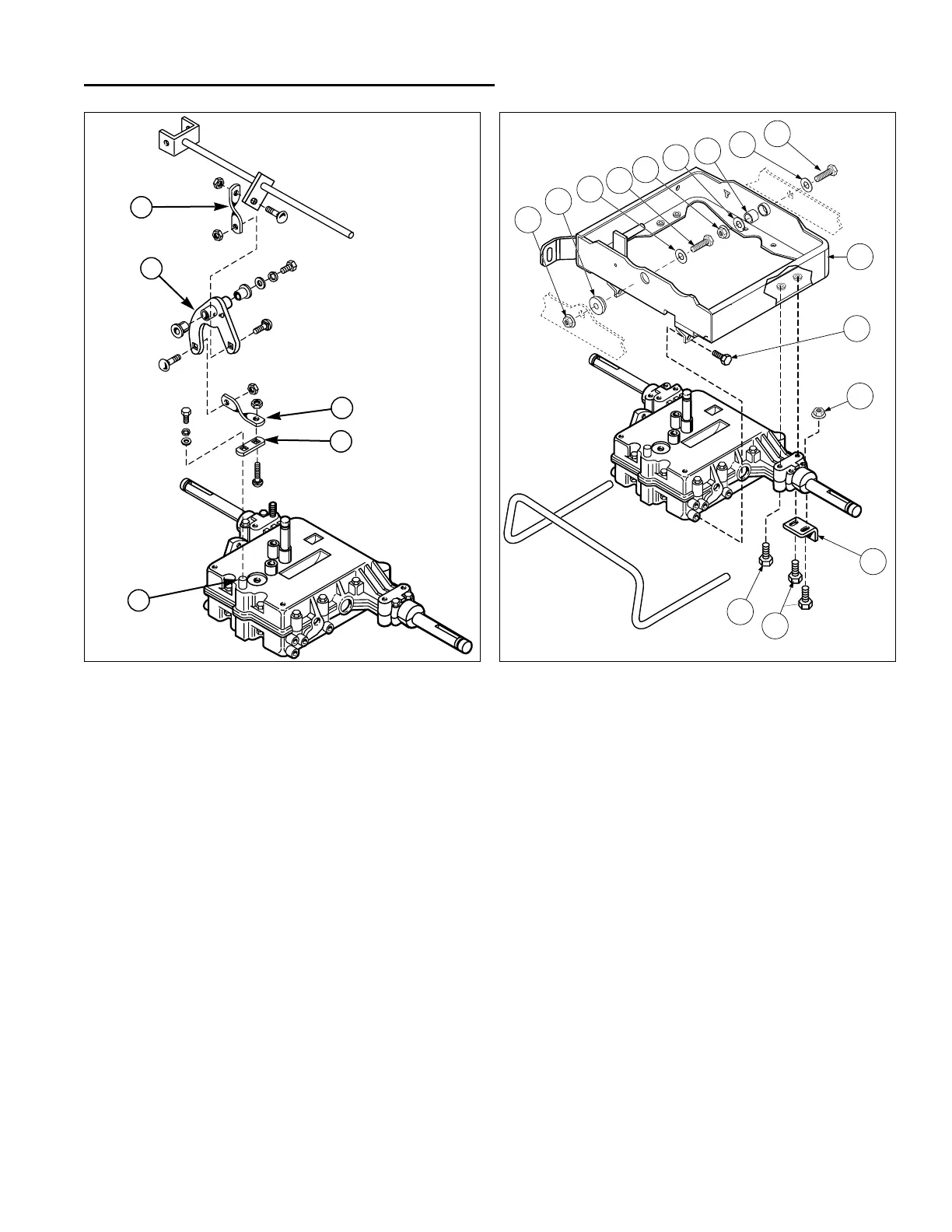
Figure 22. Peerless Shift Linkage
A. Upper Shift Link D. Shift Lever
B. Bell Crank Assembly E. Shift Shaft
C. Lower Shift Link
10 Transmission Removal & Installation
Peerless (Gear Drive) Units
A
B
C
D
E
Figure 23. Peerless Transmission & Carrier
A. Capscrew G. Capscrew
B. Washer H. Locknut
C. Spacer I. Torsion Bar Anchor
D. Flange Locknut J. Capscrews
E. Spacer K. Capscrew
F. Carrier
REMOVE THE CARRIER
If desired the carrier assembly can also be removed for
inspection.
12.Disconnect the upper shift link (A, Figure 22) from the
bell crank (B).
13.Remove the flange locknuts, capscrews, washers,
and spacers from the carrier pivot (see Figure 23).
Reinstall the carrier using the original hardware removed
in step 13. Refer to Figure 23 for assembly.
 Loading...