Instruction Manual
20220653 / Rev. C 13
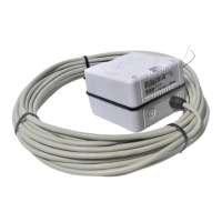
RC37 Rate Compass
RC37 is outputting heading on NMEA0183 and analog
Sine/Cosine formats.
It is a substitution for the previous RFC35RS and is a high
performance alternative to RFC35 and RFC35NS.
It comes with a 15 m (49’) open end cable wired for NMEA
input and output.
RC37 is an excellent heading source for autopilots, chart
plotters, radars and other equipment that will benefit from it’s
dynamic characteristics.
RC37 can be used with the following Simrad autopilots: AP45
(Sine/Cosine), AP9Mk3 (Sine/Cosine or NMEA0183).
Explanation to Rate Compass Block
diagram
Refer to Figure 3-2.
The rate sensor generates a rate of turn signal that is converted to
a heading angle by the integrator circuit. This output is called
Rate heading.
The heading output from the fluxgate sensor, is called Flux
heading. It is filtered by a low pass filter with a time constant
approximately three times higher than in a standard RFC35. The
Flux heading is calibrated and calibration data are stored in the
EEPROM in the compass.
The high dampening of the Flux heading will suppress unstable
heading signals caused by the vessel's roll and pitch.
The reduced response from the Flux heading is compensated for
by the Rate sensor. The Rate sensor is very sensitive to any
movement (turn) in the horizontal plane, but almost insensitive
to roll and pitch.
As the Rate heading is a relative angle it has to be coupled to the
Flux heading.
This coupling is made in the Drift Compensation circuit which
serves two purposes;
1. It will prevent the Rate heading from drifting away due to
internal (temperature) drift in the Rate sensor.