Instruction Manual
20220653 / Rev. C 31
Note 1. As RFC35N can not output Robnet and NMEA at the same time,
the connection to the autopilot has to be made by the 2-wire
p.w.m. signal (as for standard RFC35).
Note 2. RX+ (Yellow) and RX– (Green) are only used if the NMEA
equipment can send the proprietary sentences for calibration
and offset as described in Technical specifications, section 7.5
Calibration
Perform calibration as for a RFC35N compass “Connection to
other equipment” described in section 5.3, and continue with the
normal compass calibration activated from the sea trial menu in
the autopilot.
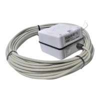
RFC35N as RFC300 substitution
When RFC35N is wired for Robnet instead of NMEA it can
substitute an RFC300 Fluxgate compass in an AP300
installation.
1. Open the RFC35N and disconnect the four wires going to J1
NMEA on the NMEA PCB and remove the cable.
2. Cut off the Robnet connector on the existing RFC300
compass cable and pull the cable through the cable gland.
3. Connect four of the six wires to J2 Robnet terminal on the
NMEA PCB according to color code in the drawing below.
Observe the color codes as there are two versions of Robnet
cables/connectors. The standard color code is used on all
removable
type connectors, while the one shown in brackets is
for molded
type connectors.
4. The two remaining wires must be isolated to avoid electrical
contact with the PCB or other terminals.