Instruction Manual
65
E04819 Issue 1.0
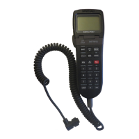
The control panel can be fitted using the adjustable stand sup-
plied or flush mounted onto a bulkhead. The stand (see Fig 7.2
above) allows the panel to be fitted to a flat surface using the
four self-tapping screws supplied and can be inverted for
mounting on an overhead surface.
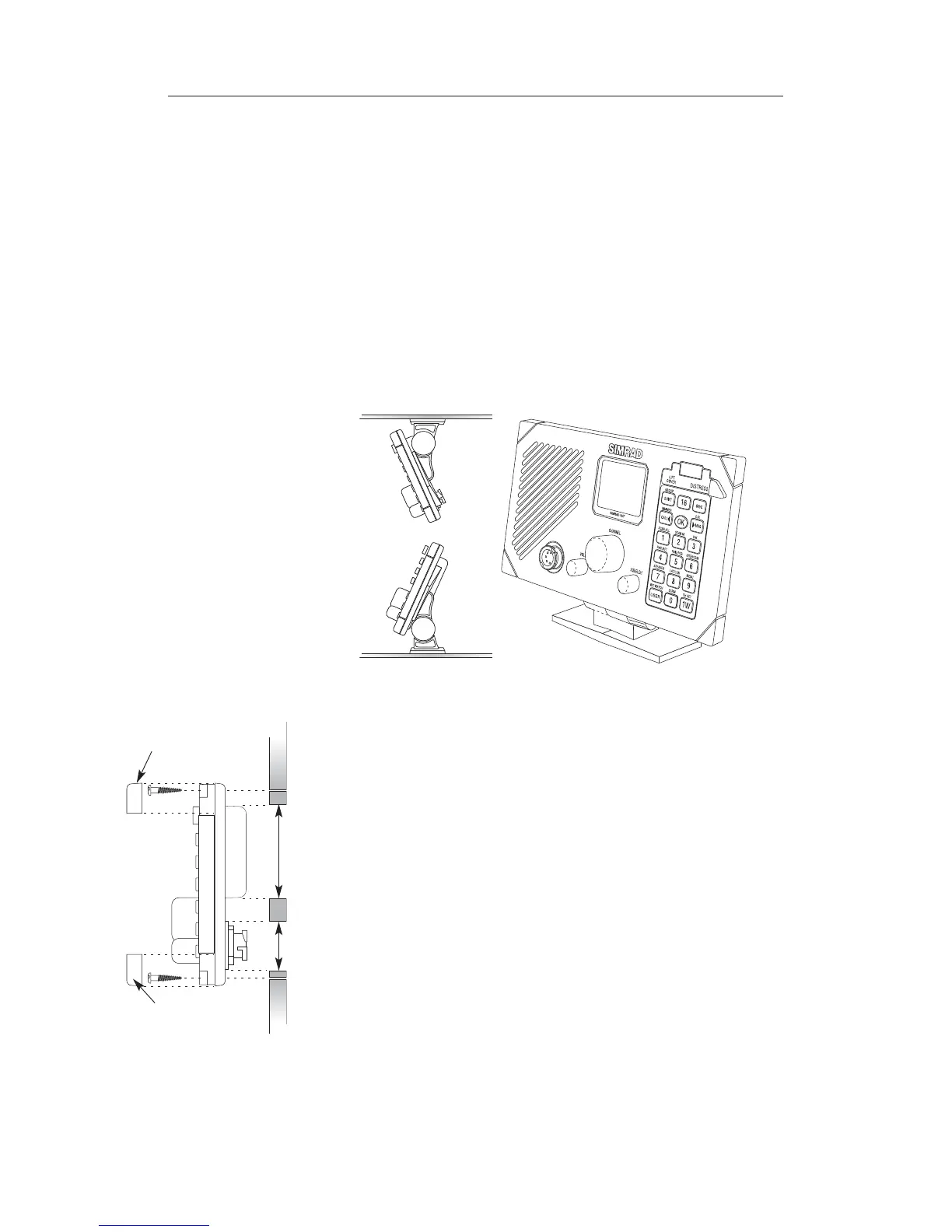
If flush mounting the panel, it is necessary to cut two holes in
the bulkhead – a 50 mm (2 in) hole for the speaker recess and a
28 mm (1.12 in) hole for the rear socket (Fig 7.3). A self-
adhesive drilling template is provided to ensure the holes are
accurately cut. Allow at least 50 mm (2 in) clearance behind the
panel for the interconnecting socket and cable. Remove the cor-
ner mouldings concealing the mounting holes and attach the
panel to the bulkhead using the four self-tapping screws provid-
ed. If fitting to a GRP surface, drill 2.5 mm (0.1 in) pilot holes
for the screws and countersink them to avoid splitting the gel-
coat.
The control panel handset/fistmike socket is waterproof, but if
the control panel is to be fitted in an exposed location (e.g. on
50mm (2.0in)28mm
(1.12in)
Corner
moulding
Corner
moulding
Fig 7.3 - Flush mounting
7.1.2 Control panel installation (RS86)
The control panel should be sited so that engine noise and
vibrations, or other background noise, do not make it difficult
for the operator to hear.
Note As microphones and loudspeakers contain powerful magnets,
the control panel, handset, or fistmike should not be installed
within 1m (3ft 3in) of any magnetic or electronic compasses.
The control panel is connected to the transceiver unit with a
5 m (16.5 ft) cable, therefore the control panel should be fitted
within reach of the transceiver (for longer runs 20 m extension
cables are available as separate accessories; see section 8.6).
Fig 7.2 - Stand mounting control panel
Overhead
mounting
Desktop
mounting