70 |
Operation | V5035 Operator and Installation Manual
2013
01
17 22:43:39
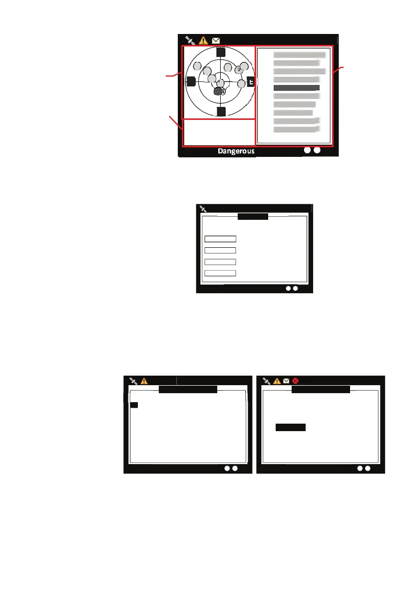
Dangerous Targets: 2
53°08’56”N
4°57’00”E
12.00Kn 241.0°
7 41
8 37
19 42
24 40
1 40
11 38
3 34
6 26
16 34
28 34
3
19
28
6
8
E
N
S
W
16
24
1
11
7
Strengt
Sate
ellite
n
Signal
ip
aon
53°08’56”N
4°57’00”E
12.00Kn 241.0°
Own Ship
informa-
tion
signal
GPS
satellite
location
signal
Strength
of GPS
satellite
signal
GPS status
Transceiver: this option provides user to view the frequencies and
status. When finished, press ESC to exit.
TRANSCEIVER
2013/01/17 22:43:39
Targets Received: 10
Receiver 1
Transmier
Receiver 2
DSC Receiver
FREQUENCY STATUS
161.975MHz OK
161.975MHz OK
162.025MHz OK
156.525MHz OK
Transceiver
Communication Test: Communication can be tested. The proce-
dure starts by transmitting Message 10 to an addressed Class A
MMSI. The addressee MMSI, once received Message 10, will return
Message 11. The test is then complete when the transponder suc-
cessfully receives the Message 11.
COMMUNICATION TEST
2013/01/17 22:44:22
Targets Received: 10
--- DEST. MMSI ---------- DATE/TIME --- RX ACK
1. 233333533 T 09:40 YES
2. 222222222 T 09:40 YES
COMMUNICATION TEST
2013/01/17 22:44:22
Targets Received: 10
PRESS ROTARY SWITCH TO SELECT
DESTINATION MMSI OF MESSAGE 10
DEST. MMSI <566884302 (19.84NM>
Communication test
Press the FUNC button to start the communication test. Following
the on-screen instruction by turn the knob to select a class A MMSI
number. Then press MENU, ESC or FUNC and click “OK” to start the
transmission of Message 10. Only Class A units with GPS fix are listed