RFC-1 Installation page 3.4
3.2.4 RP-8 Telemetry Connections
Telemetry connections to the RP-8 are made through two-conductor screw terminal connectors. The screw terminal
connectors can be removed for easier installation. There are no locks or catches, grasp the connector firmly and pull
it away from the panel.
The connector can be plugged onto the terminal posts in several directions: horizontal or vertical and left or right
facing. You may choose the position that is most convenient. Any connector orientation is acceptable but be sure to
observe proper signal polarity.
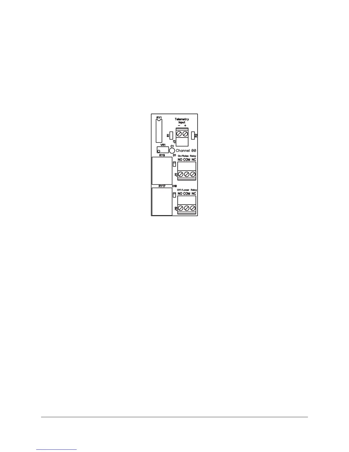
Figure 3.3; RP-8 Telemetry input connection point
Telemetry samples should conform to the following rules:
• For a full scale voltage reading a minimum of 1.0 volt DC is necessary
• Telemetry samples significantly over 5 volts DC should be dropped with an external attenuator
• Absolute maximum telemetry sample is 10 volts DC
• Telemetry samples can be offset from ground up to 30 volts DC
• Positive or negative DC voltages can be metered but not both on the same channel
More information on telemetry sources is provided later in this section.
 Loading...