RFC-1 Advanced Operation page 6.10
6.3.7 Telemetry Leading Zero Suppression
Telemetry values in the RFC-1 are four-digits long. A channel should be calibrated to take advantage of as much of
the telemetry scale as possible for maximum accuracy. Sometimes a telemetry reading will have a zero as the left
most zero in part of its operating scale. The RFC-1 can ignore leading zeros when it reports the telemetry value. The
leading zero still exists as part of the value but it is not spoken.
• Program 1 at address 0998 to enable leading zero suppression
• Program 0 at address 0998 to disable leading zero suppression
A leading zero is considered a significant digit if it occurs immediately before a decimal point. In this case the zero
will be spoken even if leading zero suppression is enabled. For example, if a channel reading is 0.951 the leading
zero is not dropped because it is significant. But it is dropped from the reading 09.51 because it is not significant.
It is important to remember that leading zeros are significant when programming alarm limits. The RFC-1 alarm
system always operates with four significant digits. Remember, leading zero suppression silences the leading zeros
but it does not remove them.
It is a common mistake to program alarm limits incorrectly when leading zero suppression is enabled. The best
method is to take a reading of the channel that the alarm will monitor and write down the numbers. If the telemetry
value is not 4 digits long, add zeros to the left of the value until it is 4 digits long. Then set the alarm limits using the
4-digit number. The following example should clarify this point.
Suppose a channel reads “99.5 percent” with leading zero suppression enabled. Alarms are to be programmed at
105.0 percent and 90.0 percent. The common mistake is to program the upper limit as 0105 for 105% and the lower
limit as 0090 for 90%. These values are incorrect because the actual channel reading is 0995. Both the upper and
lower limits are well below the normal reading. The alarm never triggers because it never even arms. The correct
upper limit in this case is 1050 and the correct lower limit is 0900.
6.3.8 Telemetry Settling Time
The telemetry settling time is a very brief delay that occurs between the selection of a channel and the sampling of
the telemetry voltage by the RFC-1 processor. The delay gives sample voltage time to stabilize before the processor
samples it. The factory setting is appropriate in most cases.
Occasionally the initial reading on a telemetry channel is slightly different, usually lower, than subsequent readings of
the same channel. Increasing the delay between the time the channel is selected and the time the RFC-1 samples
the voltage can remedy this situation.
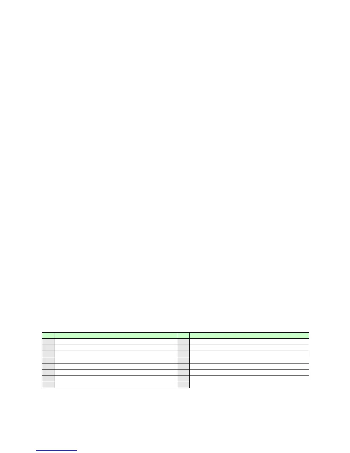
This adjustment affects all channels. If the settling time is set to a large value, there will be a noticeable pause in
between the channel selection and the telemetry value report. Program the value from the column V1 into memory
address 0997 to change the telemetry settling time.
 Loading...