RFC-1 Advanced Operation page 6.11
6.3.9 Number of Telemetry Channels Available
The RFC-1 can support up to 8 relay Panels. Each relay panel has 8 channels. Memory addresses must be
available for all 64 possible channels even though most RFC-1 systems use fewer than that. Rather than leave the
memory for unused channels empty and potentially wasted, that memory space can be used for more date/time
triggers. (Date/time triggers are discussed later in this document.)
The factory setting reserves memory for 16 channels or 2 relay panels. This is adequate for most installations.
When a third (or higher) relay panel is added memory must be swapped back for channel settings. Channel settings
can be programmed before the memory swap is performed and the data will be stored but channels will not respond
to the new settings until the memory swap is programmed.
The table below lists the available options of relay panels used (or channels available) vs. the number of date/time
triggers available. Each relay panel added reduces the available number of date/time triggers by 4. Find the number
of relay panels in use in the table below. Program the value from column V1 at memory address 1015 to reserve
memory for the appropriate number of channels.
Telemetry Channels Available
Date/Time Triggers Available
All channels use default setting (see below)
* This is the default setting.
Telemetry channels can still be used if their memory has been reallocated to date/time triggers. The channel will
behave according to the default channel setting stored at memory addresses 1020-1023. The default setting has the
same options as all other channels.
The Programming Address Table has an extra column on the right of the page titled “Alternate Use”. This column
provides the description for each memory address when used as a date/time trigger. A sample is shown below.
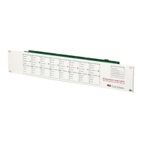
- Programming -
Addr Description Section Default Current Alternate Use / Notes
0000 Channel 00: telemetry units or status format - value 1 6.3.2 0 ____ Date/time 80: action sequence
0001 Channel 00: telemetry units or status format - value 2 6.3.2 3 ____ Date/time 80: month
0002 Channel 00: full scale and decimal point 6.3.4 2 ____ Date/time 80: date - value 1
0003 Channel 00: linear/log/indirect/invert and auto relay 6.3.5 0 ____ Date/time 80: date - value 2
0004 Channel 01: telemetry units or status format - value 1 6.3.2 0 ____ Date/time 80: hour - value 1
0005 Channel 01: telemetry units or status format - value 2 6.3.2 3 ____ Date/time 80: hour - value 2
0006 Channel 01: full scale and decimal point 6.3.4 2 ____ Date/time 80: minute - value 1
0007 Channel 01: linear/log/indirect/invert and auto relay 6.3.5 0 ____ Date/time 80: minute - value 2
 Loading...