RFC-1 Advanced Operation page 6.2
6.2.1 Programming Address Table
In the appendix of this document there is a list of all memory addresses with descriptions of what feature is controlled
at each address—the Programming Address Table. This list is the key to programming mode in the RFC-1. It
translates the memory address numbers that the RFC-1 uses into a descriptive map.
The sample below shows the first four memory addresses from the table, 0000 through 0003. The descriptions
indicate that these address control the behavior of telemetry channel 00—setting the unit word, decimal and scale.
- Programming -
Addr Description Section Default Current Alternate Use / Notes
0000 Channel 00: telemetry units or status format - value 1 6.3.2 0 ____ Date/time 80: action sequence
0001 Channel 00: telemetry units or status format - value 2 6.3.2 3 ____ Date/time 80: month
0002 Channel 00: full scale and decimal point 6.3.4 2 ____ Date/time 80: date - value 1
0003 Channel 00: linear/log/indirect/invert and auto relay 6.3.5 0 ____ Date/time 80: date - value 2
Memory is broken down into logical blocks. Similar items are grouped together so that they are easier to locate both
by users and the RFC-1. In most cases more than one address must be programmed to achieve a result. In this
example, four addresses are needed to adjust all the options available on the telemetry channel.
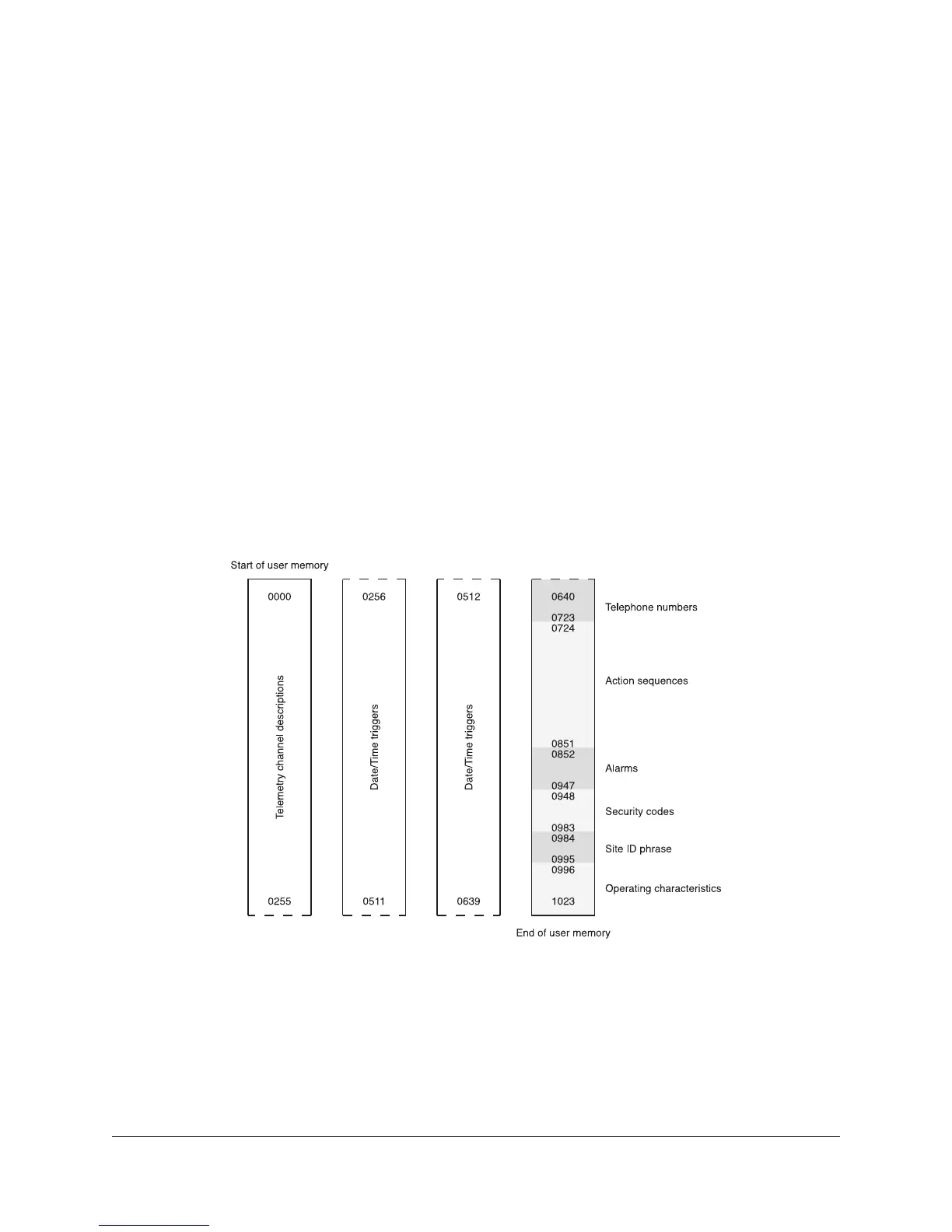
There are 1024 unique addresses. For programming purposes they are numbered from 0000 to 1023. Do not be
alarmed by the seemingly large number of addresses. They are grouped into a relatively small number of features.
The shaded areas in Figure 6.1 show how the memory map is broken down by feature. Most of the map is devoted
to telemetry channel settings and date/time functions. These are features that will be discussed shortly.
Figure 6.1; RFC-1 user memory map
Documentation in this section and the Programming Address Table must be used together. The address table has a
column titled Programming Section that gives the section number that holds the data table(s) for each address.
Additionally, each feature description gives the address or range of addresses at which that feature is programmed.
 Loading...