RFC-1 Installation page 3.7
3.3 Telemetry Source Inputs
Telemetry samples may be elevated several hundred volts above ground on some equipment.
Permanent damage may occur to the RFC-1 and/or external equipment if a high voltage telemetry
source is connected to the RP-8! Failure to observe this warning may also cause injury to the
installer or other personnel.
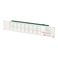
Telemetry inputs are located across the top of the RP-8 panel through the 8 two conductor terminal blocks marked
“Telemetry”. The channels are identified as “00” through “07”. In situations where more than one RP-8 is used,
channel numbers increase by 8 on each successive relay panel.
The RFC-1 will accept either a positive or negative DC voltage source as a telemetry input. One volt DC is the
minimum voltage required for a full-scale reading. A lower input voltage can be used but the maximum reading will
not reach full scale. Low sample voltages can be calibrated initially but changing readings will have steps instead of
being smooth and continuous.
Telemetry samples over 5 volts may be used but calibration accuracy suffers on analog readings. Telemetry sample
voltage is less critical for status on/off channels. Samples for status channels may be up to 10 volts DC. Telemetry
sample voltage should never exceed 16 volts DC.
Excessive telemetry sample voltage reduces the useful range of the 22 turn calibration pots to the last few turns. The
result is an overly sensitive calibration that is “touchy”—a small change of the calibration pot causes a large change
in the telemetry reading.
Telemetry samples that are significantly over 5 volts should be reduced with an external attenuator. One solution is
to add a 2.2 KΩ shunt resistor across the telemetry input terminals and a series resistor in the telemetry sample. The
series resistor should be about 2200 Ω per volt in excess of two volts. For example, to attenuate a telemetry voltage
of 10 volts, use a 2.2 KΩ shunt resistor and an 18 KΩ series resistor. The values are not critical.
The telemetry terminal blocks are polarity specific. Connect the positive (high) side of the telemetry source to the “+”
terminal and the negative (low) side to the “-” terminal. Either side may be ground referenced if necessary.
Telemetry sources may be offset from ground up to 30 volts.
Shielded wire is not normally necessary for short runs to the telemetry inputs since a considerable amount of RFI
filtering is built into the RFC-1. However, long cable runs or lines from AM sampling loops may contain a very large
amount of RF energy which can cause telemetry linearity or other problems. Excessive RF energy can burn the
telemetry input components on the RP-8. This problem can usually be eliminated by inserting 2.5 mH chokes in
series with each telemetry lead.
It makes sense for the telemetry and control on a channel to be related. If the relays on a channel are wired to
control transmitter power, then the telemetry sample on that channel should indicate transmitter power too.
There is no internal hardware connection between the telemetry input and the control I/O. It is entirely possible for a
single channel to control a function that is completely unrelated to the telemetry. System operation is not intuitive in
such a case but the RFC-1 allows this.
Channel readings do not change just because a control function is given. A sample voltage is required to indicate
any change of state. In other words, if you activate the control relay on a channel to turn on a device and there is no
telemetry sample from that device to indicate that the device turned on, the channel reading will still be “status off”.
 Loading...