RFC-1 Advanced Operation page 6.7
6.3.4 Maximum Scale and Decimal Point
Setting an appropriate scale allows the RFC-1 to give a more accurate reading. When choosing the scale, find the
smallest item in the table below that is larger than the highest expected reading. Be sure to allow some headroom for
out of tolerance readings. A telemetry channel will report “upper limit” if the reading exceeds the top of the scale,
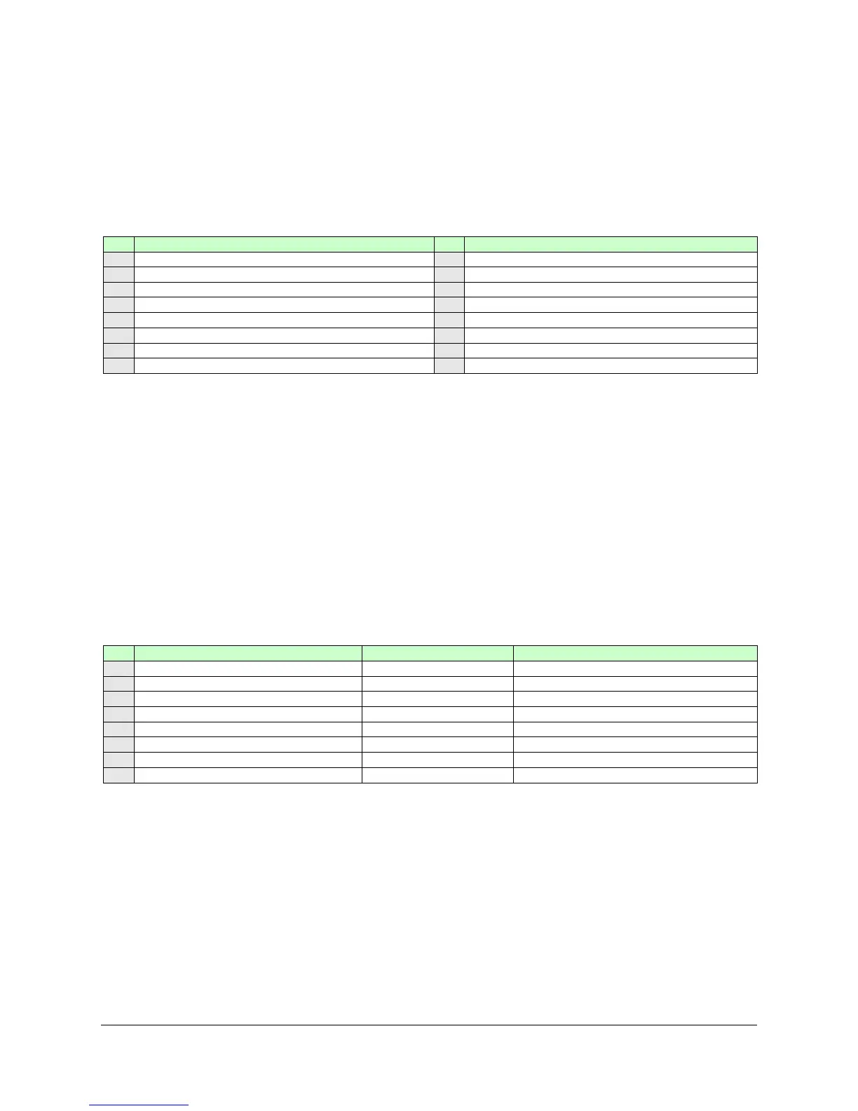
Select the maximum scale reading and decimal point location from the table below. Program the value from column
V1 into the third address for the selected channel.
Some devices generate very low sample voltages. The RFC-1 requires at least 1.0 volt DC to generate a full-scale
reading no matter which scale is selected. If the maximum sample voltage is less than 1.0 volt, the maximum
attainable reading will be proportional to the maximum voltage. For instance, if the maximum sample voltage is only
1/2 volt then the maximum attainable reading will be 1/2 of the selected scale.
6.3.5 Linear and Logarithmic Scales, Inverted Status and Auto-control Relay
As the sample voltage of a device changes, it normally follows a standard scale so that it can be tracked. The two
most common scales are linear and logarithmic. Most devices output voltages on a linear scale. Power samples are
the most common logarithmic samples but not all power samples are logarithmic. The device output determines
which scale must be used. The factory setting is appropriate in most cases.
Select the scale from the table below and program the value from the column V1 into the fourth address for the
selected channel. Limit the choice to V1=0 or V1=1 unless other specific features are needed.
Linear / Log / Indirect / Inverted
Do not program directly, use procedure
Indirect power—percent power
Do not program directly, use procedure
Inverted status described below
Auto-control relay described below
Auto-control relay described below
Auto-control relay described below
The inverted status option allows the RFC-1 to internally swap the status reported by a channel. This eliminates the
need for an external logic inverter for devices operating with negative logic. The channel must be programmed with a
status option from the table in section 6.3.3. This option modifies the behavior (changes the polarity) of that setting.
The auto-control relay feature provides an auxiliary contact for equipment that requires a switch closure to operate
properly—such as an antenna monitor. When this feature is active, the off/lower relay activates when the associated
channel is selected. The relay deactivates when another channel is selected.
Do not activate auto-control relay unless you are certain that it is necessary. Improperly activating this feature may
cause the external device to operate unexpectedly.
 Loading...