RFC-1 Accessories and Miscellaneous Circuits page 4.4
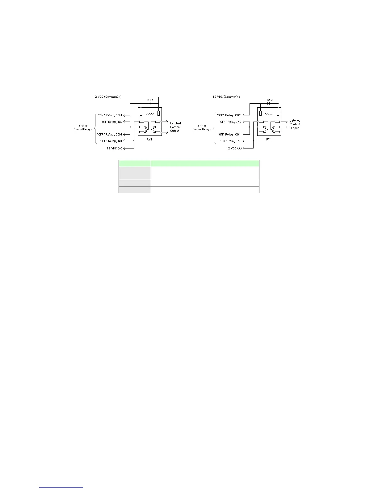
4.2.2 Latching Relays
Some devices may require a maintained relay contact for proper operation. While the RFC-1 cannot provide a
maintained relay contact, it is not difficult to use the control relays of the RFC-1 to electrically latch an outboard relay.
The disadvantage of this type of latched relay is that if power fails the relay may chatter or change state. In some
cases this is not an issue but, if it is, a mechanical or magnetically latched relay is probably a better solution.
Figure 4.2; Latched relay that powers up in the on position (left) and in the off position (right)
4.2.2 Telemetry Pulse Stretching
It is sometimes necessary to monitor a device that generates a relatively short pulse to indicate a change of status. If
the duration of the input signal is too short, the RFC-1/B may not have time to capture the pulse and respond
appropriately.
These circuits use a readily available IC, the 74HC123A, to sense the input pulse and generate an output pulse that
can last several seconds. If a second input pulse arrives before the first output pulse has completed, the output signal
timer restarts.
Do not apply an input signal greater than 5 VDC to the 74HC123A or the IC will be damaged. Use a pot or an L-pad
to reduce the input signal voltage.
Power Supply
Any regulated 5 VDC power supply should work since the IC draws very little current. The optional 100µF capacitor
should be added if a switching supply is used.
Timing Options
The duration of the output signal depends on the choice of resistor R1 and capacitor C1. The values in the schematic
produce an output pulse of about 30 seconds.
• Use C1=0.1µF and R1=5K for an output pulse of about 30 seconds
• Use C1=0.1µF and R1=10K for an output pulse of about 1 minute
• Use C1=1.0µF and R1=10K for an output pulse of about 10 minutes
 Loading...