RFC-1 Installation page 3.12
If the DC blocking capacitors are not used, however, two conditions must be satisfied:
• No more than about 50 mA DC should be drawn from this port—this is an equivalent DC load
resistance of about 240 ohms
• No DC load, and only a high impedance AC load, should be present across this port when the
RFC-1 is being operated from a dial-up line
Both of these conditions will be satisfied if an ordinary telephone is connected to this port and the telephone is left on
hook when not in use.
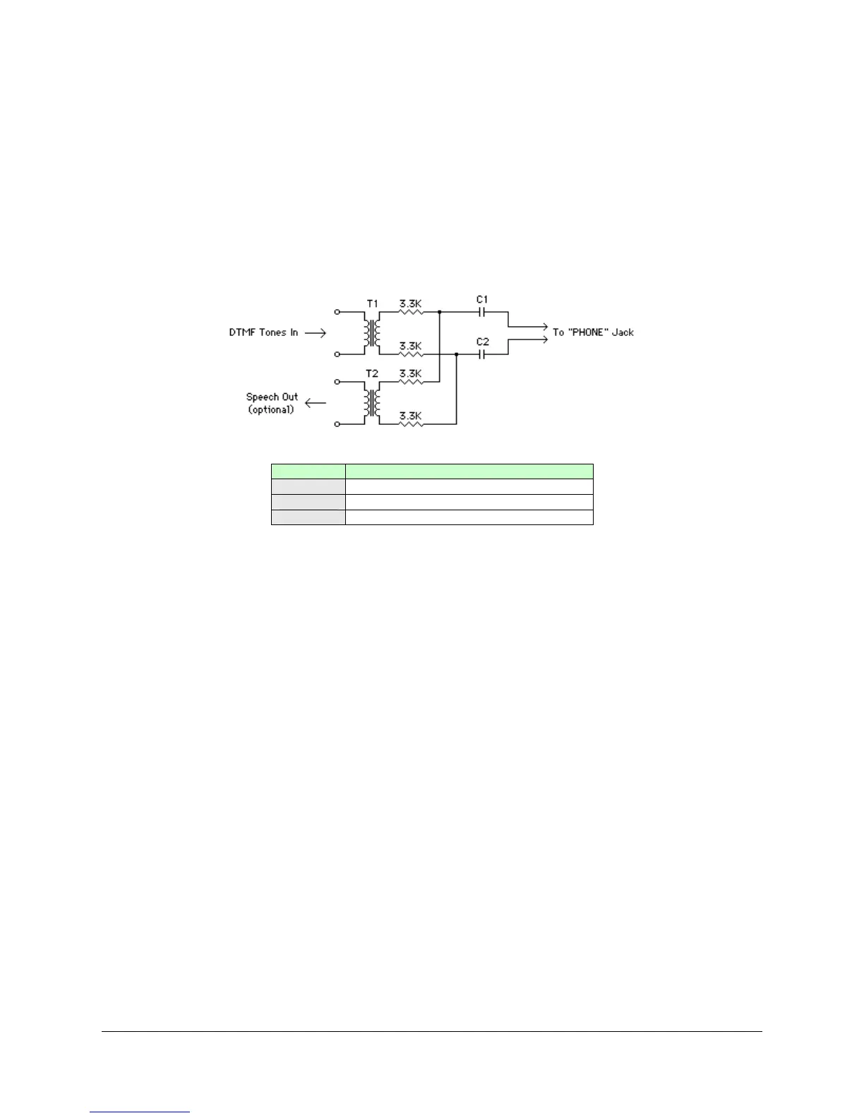
This circuit will interface a radio or other 4-wire communications link to the Dedicated Control Port.
Figure 3.12; Interface for 4-wire audio to Dedicated Control Port
C1 and C2 are used to block the 12-volt DC source. This circuit can be used with a two-way radio, a voice pager, an
SCA/STL sub-channel, or just about any communications link capable of passing voice-grade audio. It is important to
remember that operation of the RFC-1 from this port does not require the entry of the security code so the
communications link itself should be reasonably secure.
The RFC-1 will respond to any DTMF tones on this line when the Dedicated Control Port is activated. DTMF tone
used for other purposes should not appear at this port. The speech synthesizer of the RFC-1 is active on the
dedicated control port at all times and telemetry readings will be spoken as the RFC-1 scans the telemetry channels
for the monitoring and alarm system.
The proper audio level at the dedicated control port can be determined by experimentation and should be adjusted to
the minimum level required for reliable operation. In the above circuit, higher value resistors may be substituted but
do not use series resistors less than 3.3 KΩ if two transformers are used, or less than 1.5K Ω if one transformer is
used.
 Loading...