Y070.301/EN Page 13
Operation instructions
SIPOS SEVEN ECOTRON
3
Assembly and connection
3 Assembly and connection
3�3 Separate mounting
If the ambient conditions such as extreme
vibration, high temperature and/or if access is
difcult, the electronics unit is to be mounted
separately from the gear unit.
The assembly kit for mounting the gear unit
and electronics unit separately can be ordered
directly with the actuator or separately as an
accessory (2SX7300-. . .). The assembly kit is
pre-assembled. If the assembly kit is ordered
directly with the actuator, it is included separate-
ly with the actuator.
Before starting the work, disconnect actuator
from the mains!
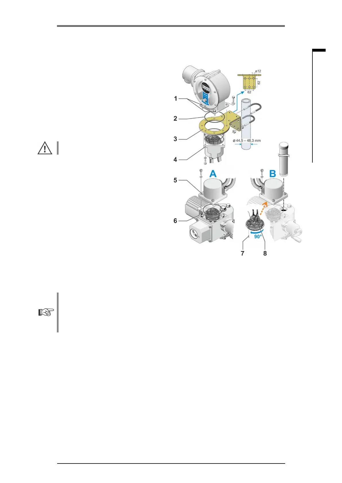
Procedure
1. Install mounting bracket (g. item 3) at the
mounting location of the electronics unit.
2. Remove electronics housing (1) from the gear
unit (6) and mount it on the mounting bracket
(3) with the O-ring (2).
3. Standard assembly, refer to A
Fit "Separate mounting“ assembly kit: Plug
cover with contact pins (4) on lower side of
wall bracket (3) and plug cover with contact
sockets (5) on the gear unit (6).
4. Assembly with stem protection tube, refer
to B
Turn connection hood by 90° or 180° to en-
sure that cables are not impaired by the stem
protection tube:
Remove screws (7) from round plug, turn
round plug by 90° to 180° and x screws
again. Continue as described in section 3.
Fig�: Separate mounting
A = Standard,
B = with stem protection tube
■
During installation, it is important to ensure that the O-rings are tted correctly in order to
guarantee the degree of protection.
■
Generally, it has to be ensured that movable parts, e.g those of the swing lever of the part-turn
actuator, are not impaired by the cables.
■
In exceptional cases, the motor might become very hot. Therefore the cables should not touch
the motor.
Specication of the connecting cable between the electronics unit and the gear unit
Mains connection: shielded and UV resistant, e.g. TOPFLEX
®
-611-C-PUR-4G1,5/11,3 cable.
TOPFLEX
®
is a trademark of HELUKABEL.
Control connection: Shielded and UV resistant, e.g. L IY11Y-7x2x0,5/11,4-S.
The connecting cables are available in different lengths:
■
Standard lengths: 3 m; 5 m; 10 m,
■
With additional equipment (lter) up to 150 m.
For separate mounting exceeding 10 m including lter, the value "Cable length exceeding 10 m
and connection via LC lter“ has to be activated for the "Separate mounting" parameter. Refer to
COM-SIPOS tab “Other"
 Loading...