Operation instructions
SIPOS SEVEN ECOTRON
Page 30 Y070.301/EN
5 Commissioning
5
Commissioning
5�3�3 Adjust speeds/positioning times
Adjust the speed/positioning time to dene the speed at which the actuator is operated. Depending
on the actuator type, different values can be set for speed/positioning time, refer to table below (ac-
tuator type and the adjustable speed range is also indicated on the name plate). New actuators are
set in the factory. Unless requested otherwise by the customer, the default parameter for CLOSE
and OPEN directions is level 4 of the 7-level setting range (step-up factor: 1.4).
If the current values are to be retained, continue with chapter „5.3.4 Select output signal set“ on
page 31.
Speed
ranges
Possible values for speed [rpm]
Indication in the
display ►
■□□□□□□□ ■■□□□□□□ ■■■□□□□□ ■■■■□□□□ ■■■■■□□□ ■■■■■■□□ ■■■■■■■□
1,25 – 10 1.25 1.75 2.5 3�5 5 7 10
2,5 – 20 2.5 3.5 5 7 10 14 20
5 – 28 5 7 10 14 20 28 ---
5 – 40 5 7 10 14 20 28 40
10 – 80 10 14 20 28 40 56 80
20 – 112 20 28 40 56 80 112 ---
20 – 160 20 28 40 56 80 112 160
Positioning time for part-turn actuator 2SG7 and 2SQ7
Positioning time
range
Possible values for positioning time [s/90°]
80 – 10 80 56 40 28 20 14 10
▲
Level 4 is set as standard.
Operation sequence
The actuator is in the ‘Parameter‘ menu.
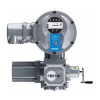
1. Turn Drive Controller until symbol for speed
is blinking (g. 1, item 2).
The black segment in the scale, g. 1,
item 1, indicates the currently set speed/po-
sitioning time level, see also table above.
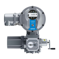
2. Press Drive Controller.
The black segments in the scale are
blinking (g. 2).
3. Turn Drive Controller and selected desired
speed/positioning time level.
The scale indicates the selected level (g. 2,
item 1).
4. Press Drive Controller.
The parameter value of the selected level is
accepted and the speed symbol is blinking.
Now, one of the 4 output signal sets can be
selected. Turn Drive Controller until the symbol
for signal set is indicated.
Fig� 1: Speed/positioning time level
Fig� 2: Change speed/positioning time level
 Loading...