Y070.301/EN Page 17
Operation instructions
SIPOS SEVEN ECOTRON
4
Instructions on operator control and operation
4 Instructions on operator control and operation
= LED is not illuminated (off)
= LED is illuminated
= LED is continuously ashing
3 x
= LED is ashing periodically. The ashing, here 3 times, is repeated after a pause
of 1 s: 3 x ashing + pause = 1 period
LED
Signication Corrective actions
Fault
type
(green)
(red)
The actuator is ready for operation.
Fault: commissioning is invalid
Perform commissioning.
Refer to „5 Commissioning“ on page 25.
N
2x
Fault:
Motor temperature too high
■
Check valve for sluggishness.
■
Reduce number of starts.
■
Ambient temperature impermissibly high
■
Check "Separate mounting“ parameter
using COM-SIPOS.
S
3x
Fault:
Mains failure or excessive mains
voltage uctuations.
Check supply voltages. S
4x
Fault: Open-circuit behavior of
■
Travel potentiometer/non-intrusive
position encoder or temperature
sensor;
■
feed cables from REMOTE.
■
Check cables for separate installation.
■
Check cables (eldbus, if applicable)
S
5x
Fault:
Travel is blocked, i.e. tripping torque
reached within travel.
Actuator can still be operated into the
opposite direction (leaving the block)
■
Check valve for sluggishness.
■
Increase torque values.
■
Check "Separate mounting“ parameter
using COM-SIPOS.
S
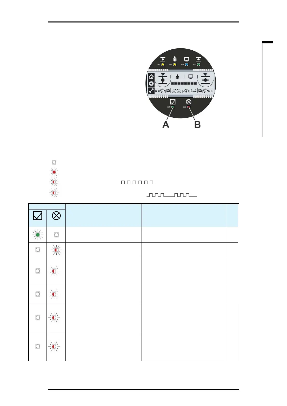
4�2�3 Status and fault signals
LEDs ”Ready“ (g. item A) and the ”Fault“
(Pos. B) indicate the device state and the
signals during faults. This enables an analysis
of the faults. Some of the "Fault signals” can be
reset, refer to right column "Fault type" in the
following table.
The symbols have the following meaning:
■
S – automatically resetting fault signals
Once the cause of the fault is eliminated, the
fault signal is automatically reset.
■
N – Non-resettable fault signals.
The cause of the fault must be eliminated.
The table below lists possible states of the
“Ready” and “Fault” LEDs and the respective
signications as well as corrective actions. The
states of the LEDs (off – illuminated – ashing)
are represented in the operation instructions as
follows:
Fig�: A = LED ”Ready“ and
B = LED ”Fault“
 Loading...