Y070.301/EN Page 19
Operation instructions
SIPOS SEVEN ECOTRON
4
Instructions on operator control and operation
4 Instructions on operator control and operation
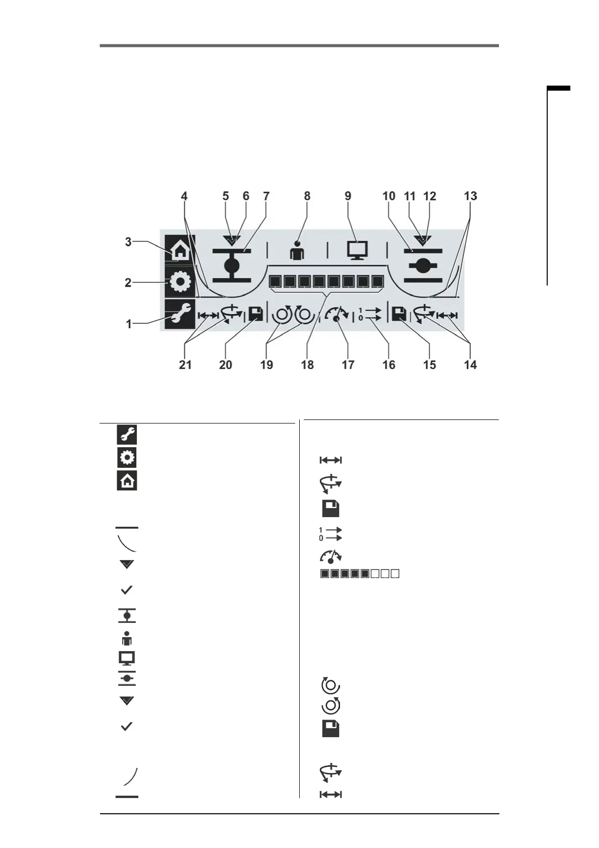
4�3 Display
The graphic segment display utilizes different symbols to indicate the actuator state during
operation, commissioning and parameterization. Clear representation and unambiguous symbols
enable simple operation. The Drive Controller (rotary push button) enables operation directly at the
actuator.
This chapter provides an overview of symbols in the display and the information they provide for the
user. Once acquainted with the signication of the symbols, actuator operation is quick and easy.
Fig�: Segment display
Item Description on page ▼
14
Setting of the cut-off mode in end posi-
tion OPEN:
37
Travel dependent cut-off mode
or
37
Torque dependent cut-off mode 37
15
Save settings for end position
OPEN
37
16
Output signal set for binary
outputs and control mode
31
17
Speed 30
18
Scale shows
■
depending on the preselected
function; the setting for
– tripping torque
– output speed
– output signal set
– control mode
■
the position during travel
28
30
31
32
21
19
Closing direction adjustment:
clockwise or 37
counterclockwise 37
20
Save settings for end position
CLOSED
37
21
Setting of the cut-off mode in end
position CLOSED:
Torque dependent cut-off mode 28
Travel dependent cut-off mode 37
Item Description on page ▼
1
Parameterization menu 28
2
End position adjustment menu 37
3
Local operation menu 22
4
Indicates the cut-off mode in CLOSE
direction:
Travel dependent or
38
Torque dependent 38
5
Indicates that end position
CLOSED is selected
37
6
Tick conrms correct end posi-
tion adjustment
37
7
Symbol for end position
CLOSED
37
8
LOCAL mode 22
9
REMOTE mode 22
10
Symbol for end position OPEN 37
11
Indicates that end position
OPEN is selected
37
12
Tick conrms correct end posi-
tion adjustment
37
13
Indicates the cut-off mode in OPEN
direction:
37
Torque dependent or
Travel dependent 37
 Loading...