Y070.301/EN Page 31
Operation instructions
SIPOS SEVEN ECOTRON
5
Commissioning
5 Commissioning
5�3�4 Select output signal set
You may dene which output signals are present at the 5 signal outputs. You may choose between
4 output signal sets (consisting of predened output signals for each of the 5 signaling outputs).
Output signal
sets
Indications on
display
Signaling
outputs
Level*
Signal Explanation
Set 1
(defaut setting)
■□□□□□□□
1
H a Travel OPEN
a Travel OPEN:
For travel-dependent cut-off in position 100 % OPEN;
for torque-dependent cut-off in position >= 98 % OPEN.
b Travel CLOSE:
For travel-dependent cut-off in position 0 % ;
for torque-dependent cut-off in position >= 2 % OPEN.
c Torque OPEN/CLOSED reached:
For torque-dependent cut-off within end position range OPEN
or CLOSED.
d
Ready + REMOTE
If the actuator can be operated from REMOTE.
e Warning motor temp�:
If the set motor warning temperature (default: 135 °C) has
been reached.
f, g End position OPEN, end position CLOSED:
For travel-dependent cut-off in position 100 % OPEN/ 0 %
OPEN.
For torque-dependent cut-off,
if tripping torque within end position range (>= 98 % OPEN/
<= 2 % OPEN) is reached.
h Blinker:
0.5 Hz-change between high/low level if the actuator is
operated (low at standstill).
j Fault:
If a fault has occurred.
k Local:
Actuator is in position Local.
l
Torque OPEN reached:
If tripping torque in OPEN direction is reached.
m Torque CLOSE reached:
If tripping torque in CLOSE direction is reached.
2
H b Travel CLOSE
3
L c Torque OPEN/CLOSE reached
4
H d Ready + REMOTE
5
L e Warning motor temperature**
Set 2
□■□□□□□□
1
H f End position OPEN
2
H g End position CLOSED
3
H h Blinker
4
H d Ready + REMOTE
5
L i Warning motor temperature**
Set 3
□□■□□□□□
1
H f End position OPEN
2
H g End position CLOSED
3
L j Fault
4
H k Local
5
L i Warning motor temperature**
Set 4
□□□■□□□□
1
H a Travel OPEN
2
H b Travel CLOSE
3
H d Ready + REMOTE
4
L l Torque OPEN reached
5
L m Torque CLOSE reached
* H = active high: supply voltage binary output,
L = active low: 0 V).
Level active high or active low is set when reaching the status.
** for 2SG7... “Fault motor temperature”
Operation sequence
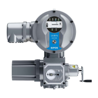
1. Turn Drive Controller in the ‘Parameter’
menu until symbol for speed is blinking
(g. 1, item 2).
A black segment indicates the current
set within the rst four digits of the scale
(item 1); in g.1, set 4 is selected (see also
table above).
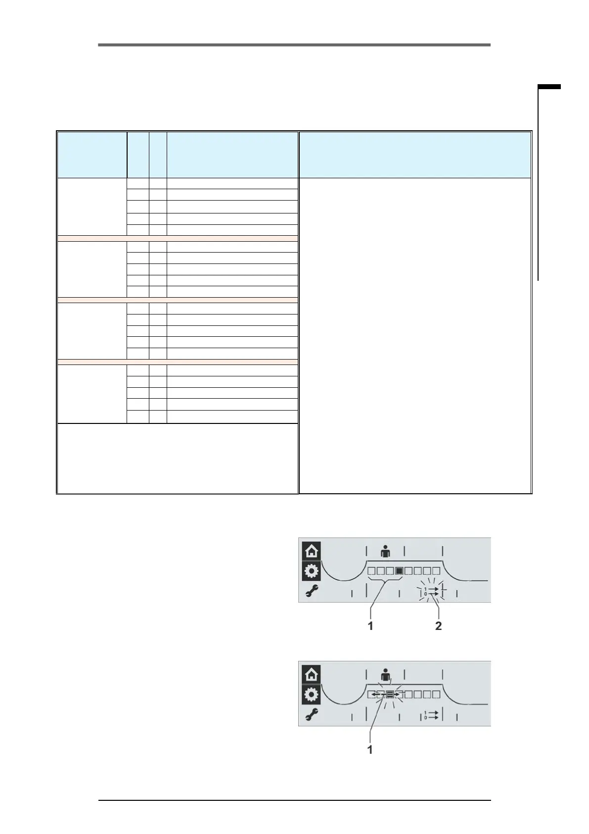
2. Press Drive Controller.
The black segment, which indicates the ad-
justed output signal set, is ashing (g. 2).
3. Turn Drive Controller and select desired
signaling set (g. 2, item 1).
The segment in the scale indicates the se-
lected output signal set; the rst position on
the left stands for output signal set 1.
4. Press Drive Controller.
The parameter values of the selected output
signal set are accepted and the black
segment for the selected output signal set
is continuously illuminated and the control
mode options are available.
Refer to following section.
Fig� 1: Indication of output signal sets
Fig� 2: Output signal set selection
 Loading...