Do you have a question about the SIPOS SEVEN 2SA7 and is the answer not in the manual?
Provides essential safety instructions and warnings for operating the actuators.
Details on how to safely transport and store the actuators.
Provides notes on using the operation instructions and explains symbols.
Defines the scope and limitations of the operation instructions.
Lists supplementary operation instructions for specific components or features.
Explains the basic functional principle of the electric actuators and their components.
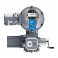
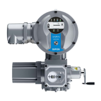
Describes the main sub-assemblies of the SIPOS SEVEN actuators.
Provides a block diagram illustrating electrical connections for actuators.
Instructions for mounting the actuator to a valve or gear unit.
General instructions applicable to all output shaft types during assembly.
Specific assembly instructions for output shaft type A.
Instructions for mounting the stem protection tube.
Details on how to perform electrical connections for the actuator.
Instructions for making electrical connections using a round plug.
Instructions for establishing a fieldbus connection to the actuator.
Procedures for connecting the external potential conductor for grounding.
Instructions for mounting the electronics unit separately from the gear unit.
Explains the operation using the crank handle and hand wheel.
Overview of LEDs and the display for actuator status indication.
Details the meanings and functions of the light emitting diodes (LEDs).
Explains the different display areas and status indications.
Explains texts and symbols used in the actuator's status indication display.
Describes end position symbols and how position bars indicate actuator status.
Details how to interpret the actuator status displayed on the device.
Lists status messages and their corresponding explanations and possible remedies.
Explains how to navigate through the actuator's menu system using the Drive Controller.
Details the operation sequences for using the Drive Controller for menu navigation.
Explains symbols, texts, and graphical elements found within the actuator's menus.
Describes the process for step-by-step parameter setting.
Explains how to perform digit-based setting for parameters.
Explains how to change the actuator's control mode (Local, Remote, Off).
Details how to operate the actuator locally using the 'Local operation' mode.
Describes the 'Remote' control mode where the actuator is managed by an automation system.
Explains the 'Off' control mode where actuator operation is not possible.
Instructions for selecting the display language for the actuator.
Provides an overview of the main menu items and their functions.
General information on user levels and access authorization for actuator functions.
Steps for assigning or changing passwords for different user levels.
Instructions on how to enable specific user levels for accessing functions.
General information and safety precautions prior to commissioning the actuator.
Outlines the sequence of actions required for actuator commissioning.
Explains the functional principle and use of additional gears with actuators.
Steps to select an additional gear and adjust its parameters.
Details the parameters and their possible values for additional gears.
Specifies the maximum output torque or force for additional gears.
Specifies the maximum input speed for additional gears.
Defines Rev./stroke, positioning angle, or stroke for additional gears.
Describes the signaling gear setting for actuators with signaling gears.
Configuring closing direction, speeds, cut-off modes, and tripping torques.
Instructions for selecting and changing the actuator's closing direction.
Details on programming actuator speeds and positioning times.
Configuring cut-off modes and tripping torques or forces.
Explains how the set cut-off mode is indicated and its default value.
Details on setting tripping torques and forces based on actuator sizing.
Adjusting end positions for actuators equipped with a signaling gear.
General information and prerequisites for adjusting actuator end positions.
Illustrates the schematic representation of signaling gear ratio and end position settings.
Details how to determine and set the signaling gear ratio.
Step-by-step procedure for the initial adjustment of actuator end positions.
Illustrates turning the central wheel to the mid-position during end position adjustment.
Shows the display for selecting the end position to be set.
Illustrates approaching the end position in the OPEN direction.
Describes approaching the end position using travel-dependent cut-off mode.
Describes approaching the end position using torque-dependent cut-off mode.
Illustrates adjusting the central wheel during end position adjustment.
Confirms the correct setting of the first end position.
Illustrates approaching the CLOSED end position in travel-dependent mode.
Indicates when the end position range has been exceeded during adjustment.
Illustrates approaching the CLOSED end position in torque-dependent mode.
Confirms the successful end position setting.
Procedure for readjusting previously set end positions.
Shows the display for end position adjustment.
Illustrates the selection of an end position for readjustment.
Guides the user to approach the new end position.
Shows how to accept the adjusted end position after adjustment.
Confirms that the end position readjustment was successful.
Instructions for adjusting the mechanical position indicator.
Shows the symbols used for OPEN and CLOSED positions on the indicator.
Illustrates the process of adjusting the mechanical position indicator.
Shows the position indicator specifically for the 2SG7 model.
Shows the position indicator specifically for the 2SQ7 model.
Adjusting end positions for actuators with a non-intrusive position encoder.
Initial setting procedure for end positions with a non-intrusive encoder.
Displays the interface for end position readjustment.
Shows end position setting options, with or without full parameters.
Illustrates the selection of an end position for adjustment.
Guides approaching the OPEN end position.
Shows how to accept the adjusted end position.
Illustrates approaching the CLOSED end position.
Indicates when the CLOSED end position has been reached.
Displays the end position adjustment interface.
Shows the selection of an end position for readjustment.
Illustrates approaching and accepting a new end position.
Confirms that the end position readjustment was successful.
Provides an overview of the parameter menu structure for actuator configuration.
Lists and describes parameters that directly affect the valve's operation.
Instructions for changing parameter characteristics within the 'Valve' menu.
Details how to change numerical values for parameters like tripping torque.
Lists default values and settings for valve-specific parameters.
Describes the parameter for setting the end position range.
Explains the parameter for handling torque blocks and retries.
Overview of parameters for integrating the actuator with control systems (DCS).
Lists possible parameters within the Control System menu.
Describes the procedure for changing parameters in the Control System menu.
Explains how to set the control mode for the actuator via the control system.
Details the binary control modes available for DCS integration.
Explains the analog control modes for DCS integration.
Describes fieldbus control modes for DCS integration.
Explains the internal control mode for DCS integration.
How to set up an alternative control mode for the actuator via DCS.
Configuration of binary inputs for control system integration.
Functions controlled by the MODE input for system integration.
Setting up analog input AI1 for setpoints or speed control.
Configuration of analog input AI2, if available.
Details on the 8 available binary feedback outputs for the control system.
Configuration options for signaling output 1.
Configuring analog output AO1 for feedback signals.
Illustrates blinker and end position signaling for binary outputs.
Configuration of analog output AO2, if available.
Details on configuring the PROFIBUS DP interface for DCS integration.
Configuration settings for the MODBUS interface.
Configuration settings for the HART interface.
Describes how EMERGENCY operation can be triggered.
Configuration of the EMERGENCY input signal.
Setting the actuator speed during EMERGENCY operation.
Setting the actuator's position during EMERGENCY operation.
Defines actuator behavior upon loss of control signal.
Steps to enable optional software functions and customer variants.
Details on the Positioner software function for precise control.
Configuration of the Proportional move function for actuator operation.
Lists and describes various optional software functions available for actuators.
Visual overview of the Special Parameters menu.
Instructions for entering a tag number for plant identification.
Parameter for setting up separate mounting of electronics and gearbox.
Defines setting ranges for intermediate contact signals.
Settings related to motor heating, warning, and protection.
Settings for planning valve maintenance based on operating hours or cycles.
Enables or disables the check for maintenance limits.
Function to ensure the actuator closes tightly.
Parameter to adjust the rise time for speed control.
Setting for the DC brake function to stop the motor.
Sets a delay time for power failure messages to avoid false alarms.
Configures the use of a torque measurement flange.
Sets thresholds for detecting wire breaks in analog outputs.
Enables a continuous test operation cycle for the actuator.
Limits the DC link voltage to prevent issues during standstill.
Monitors actuator runtime and detects errors.
Sets the speed at which the actuator operates within end position ranges.
Configures a quick start function for faster leaving of end positions.
Configures a quick start and stop function for approaching end positions.
Automatically adapts end positions to compensate for wear or temperature changes.
Sets the acceptance time for signals from the DCS.
Settings related to the actuator's display.
Adjusts the display orientation for better legibility.
Selects the information shown on the display in standby mode.
Enables immediate local operation of the actuator.
Sets the time interval before the display enters standby mode.
Manually activates the display's standby mode.
Adjusts the actuator's date and time settings.
Manages the activation and deactivation of the Bluetooth function.
Information on using a remote control unit for actuator operation.
Steps to activate the remote control unit function for the actuator.
General information on recording and comparing torque curves for preventive monitoring.
Step-by-step procedure for recording a torque curve directly on the actuator.
Instructions for saving recorded torque curves to a USB flash drive.
Displays information from the actuator's electronic name plate.
Shows the tag number entered for plant identification.
Lists the actuator's order number and equipment characteristics.
Displays the serial number of the current electronics unit.
Shows the original serial number of the electronics unit.
Displays the current firmware version number and issue number.
Displays the status of binary and analog inputs and outputs.
Shows the voltage level of binary inputs (CLOSE, OPEN, STOP, etc.).
Displays measured currents for analog inputs and outputs.
Indicates if torque switches are active for 2SQ7 models.
Displays status of fieldbus communication (PROFIBUS DP).
Displays status of Modbus communication.
Displays status of HART communication.
Provides current operating data like speed, torque, temperature, and status.
Procedure for adjusting the torque zero point when using a torque measurement flange.
Displays operational data such as switching cycles and motor operating hours.
Shows defined limits for valve maintenance based on cycles or hours.
Indicates whether valve maintenance is necessary or has been reset.
Methods for controlling the actuator remotely via DCS or fieldbus.
Overview of the COM-SIPOS software tool for actuator configuration and monitoring.
Information on connecting to the actuator via the USB port.
Describes how to exchange data with the actuator using a USB flash drive.
Instructions for updating the actuator's firmware via USB.
Saving actuator parameters, settings, and operational data to a USB drive.
Loading customer-modifiable parameters from a USB drive back to the actuator.
Refers to saving torque curves to a USB flash drive.
Function to duplicate actuator parameters to a new electronics unit.
General safety guidelines and recommendations for actuator maintenance.
Information on lubrication intervals and types of lubricants for actuators.
Details lubricant quantities and assignments for different actuator types.
General information on ordering and identifying spare parts.
Lists recommended spare parts for actuators, including part numbers.
Exploded views of the gear unit 2SA7... showing component identification.
Exploded view of the 2SA7... gear unit, detailing its components.
Exploded view of the 2SG7... small part-turn gear unit.
Exploded view of the 2SQ7... small part-turn gear unit.
Exploded views of the electronics unit for different motor sizes.
Declares conformity with Machinery and Low Voltage Directives.
| Brand | SIPOS |
|---|---|
| Model | SEVEN 2SA7 |
| Category | Controller |
| Language | English |