Y070.302/EN Page 11
Operation instructions
SIPOS SEVEN: PROFITRON, HiMod
3
Assembly and connection
3 Assembly and connection
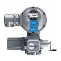
1. Unscrewcenteringring(g.,item5)from
outputange.
2. Take off stem nut (4) together with axial
needle-roller assembly and axial bearing
washers (3).
3. Remove the axial needle-roller assembly and
the axial bearing washers (3) from the stem
nut.
4. Only if the stem nut was delivered without
thread: Cut a thread in the stem nut (4)
(check the concentricity and the axial run-out
when clamping the stem nut) and clean it.
5. Lubricate axial needle-roller assembly and
axial bearing washers (3) with ball bearing
greaseandtthemonthenewormachined
stem nut (4).
6. Insert stem nut (4) with axial needle-roller
assemblyintooutputange(clawshaveto
engage properly into the groove of the output
shaft of the actuator).
7. Screw in the centering ring (5) and tighten it
to the stop. Make sure that the radial shaft
seal (6) is inserted correctly.
8. Using a grease gun, press ball bearing
grease into the nipple until lubricant is dis-
charged between the centering ring (5) and
the stem nut (4).
For output shaft form A, ensure that the valve stem is greased separately!
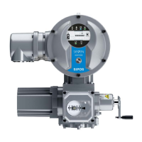
3�1�3 Mount stem protection tube
1. Removefastener(g.,item1).
2. Check that the extended stem does not ex-
ceed the length of the protection tube.
3. Apply sealing compound to the thread and
the sealing faces (e.g. 732 RTV from Dow
Corning, Munich, Germany).
4. Screw in the stem protection tube (2).
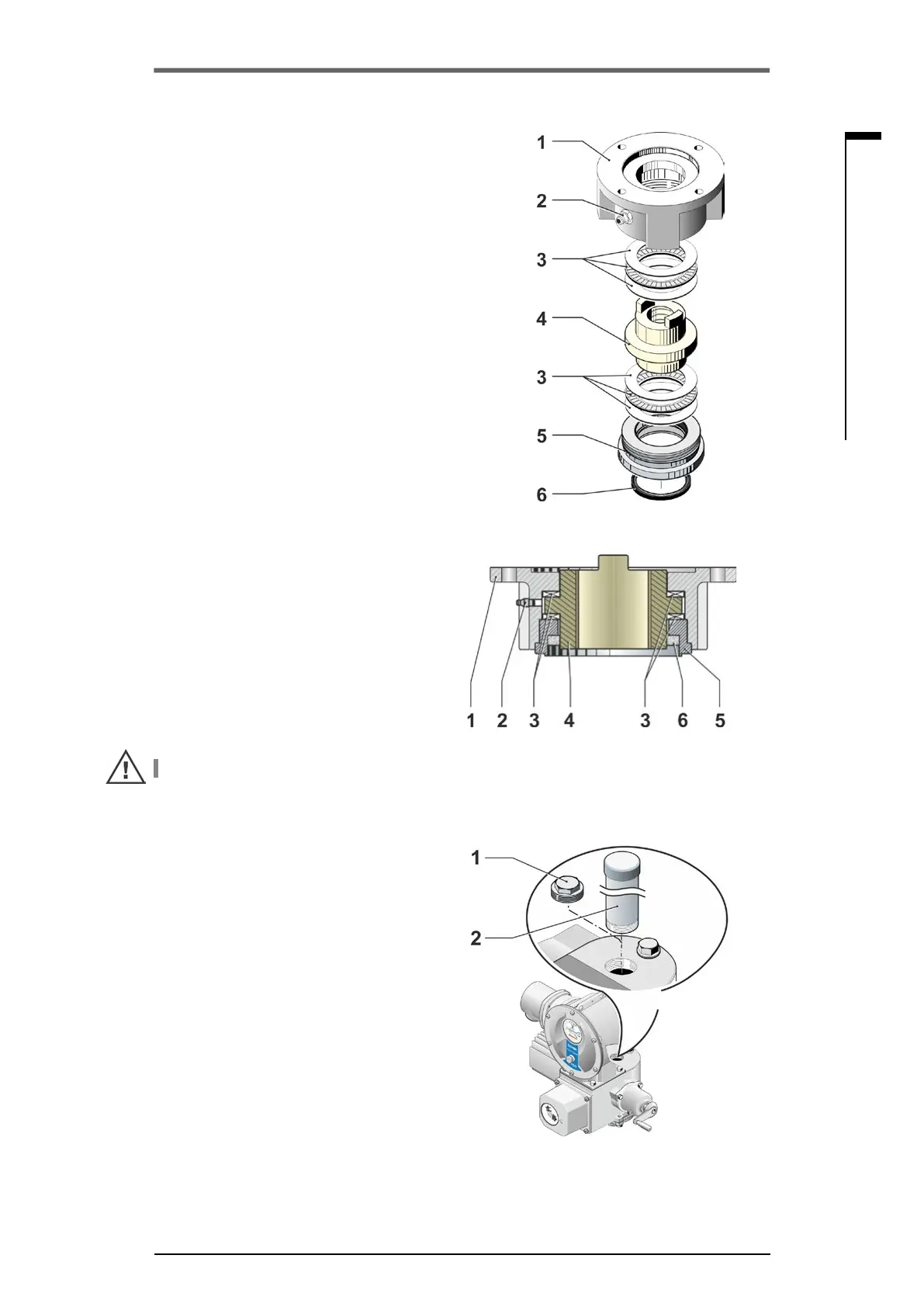
Fig�: Output shaft type A installed
Fig�: Mount stem protection tube
Fig�: Output shaft type A
assembly